MP2715 Computer Aided Design and Simulation Assignment Sample
Advanced MP2715 Computer Aided Design & Simulation assignment sample with CAD hardware, FEA, and centrifugal clutch design analysis for engineering students
- 92650+ Project Delivered
- 1500+ Experts 24x7 Online Help
- No AI Generated Content
Introduction Of Computer Aided Design and Simulation Assignment
The centrifugal clutch is the key component in small engineering applications to engage power transmission based on increasing engine speed. The key advantage is the ability to smoothly and automatically engage without manual intervention. To achieve optimal performance, the GX100 engine, used in lightweight machinery, requires a clutch that works well with the PTO shaft of Q type; or more accurately. This study, presents a particular centrifugal clutch design and analysis of this clutch. The objectives include a detailed CAD model creation, motion analysis to validate engagement and FEA analysis to assess stress and strain. The goal of these is a safe, durable, and efficient clutch design.
CAD Hardware Requirements
To efficiently model and simulate 3D problems, and to conduct Finite Element Analysis (FEA), CAD systems demand robust hardware configurations. Key hardware components include the following:
- Processor: The central processing unit (CPU) is key to completing the computational tasks in CAD and FEA (Panchal et al. 2023). High clock speeds and multi-cores are economies of modern CAD software. For detailed 3D modelling and simulation process, a recommended CPU for this purpose will have to be a multi-core processor that comes with more than 3.5 GHz.
- RAM: There must be enough Random Access Memory (RAM) to process massive CAD files and multitask. The minimum requirement for RAM offered for industrial CAD systems will also be 16 GB, and 32 GB is recommended for handling simulation data and large assemblies.
- Graphics Card: The rendering speeds and graphical accuracy of CAD are improved by a powerful Graphics Processing Unit (GPU). For 3D wireframe, surface, and solid modeling, recommend workstation-grade GPUs, such as NVIDIA Quadro, or AMD Radeon Pro. Most tasks can be done with a dedicated GPU with 4 GB VRAM or more, but 8 GB is the best available for the most advanced simulations.
- Storage: Solid State Drives (SSD) are fast storage solutions which trim down the load times and can give access to big project files quickly (Wang et al.2021). Complementing a minimum of 512 GB SSD storage is a secondary hard disk drive (HDD) for long-term data storage.
Types of CAD Software
CAD software is categorized based on its functionality:
- 2D Drafting: Great for simple layouts, technical drawings and schematics.
- 3D Wireframe Modeling: It presents a skeletal representation of designs for visualization of geometric structures.
- Surface Modeling: Designed to create intricate surfaces that would be suitable for automotive and aeronautical designs.
- Solid Modeling: Since it is the most versatile image, it can be created with it for detailed and realistic 3D representation of mechanical components (Ni, 2024).
The hardware specifications provide efficient handling of CAD tasks and integration of model, simulation, and analysis processes.
Struggling with deadlines? Turn to New Assignment Help for reliable Best Assignment Help that takes the pressure off and boosts your academic success.
Design Methodology
Initial Design Concept
A centrifugal clutch design was developed that could achieve a reliable and efficient engagement mechanism with safety and durability. The other was the entering RPM where the clutch starts slightly engaging below the 1000 RPM which the engine is operating on until it enters the working range (Li et al.2024).
The material selection was critical because each component was subjected to mechanical stresses, thermal loads and environmental wear. The Q type shaft was chosen to be from stainless steel for strength, corrosion resistance, and durability to rotational loads. For the shoes, high friction, wear resistance, and thermal stability were provided through the use of ceramic material. Using Finite Element Analysis (FEA), stress concentrations in the shoes and support components were carefully examined to address safety.
High-performance rendering and complex engineering simulations are increasingly being processed off-site using scalable remote servers. To explore how heavy data processing is managed over high-speed networks, you can consult our Cloud Computing Assignment Help
The clutch also proved to be modular in design, simplifying maintenance, and optimal to the GX100 engine’s PTO shaft.
3D Modeling
CAD representations of the detailed components were made, and their parts were assembled into a functional clutch model through a 3D modelling process. Accurate modelling and assembly were possible with the design software.
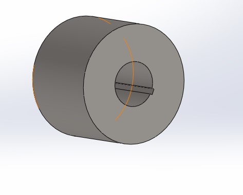
Figure 1: Clutch hub
Shaft: A shaft of the GX100 engine was modelled. Adoption features include a keyway that helps to improve functionality.
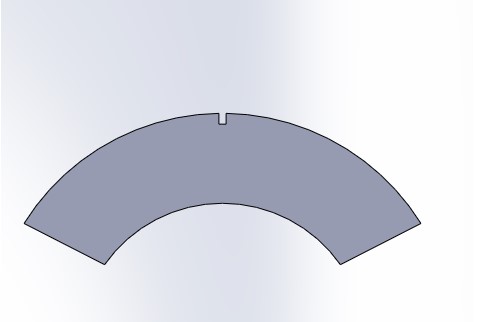
Figure 2: Flyweight
Shoe: The frictional contact surface of the designed clutch shoe is curved (Cao et al.2024). It has a geometry that confirms uniform engagement with the drum when it is in operation.
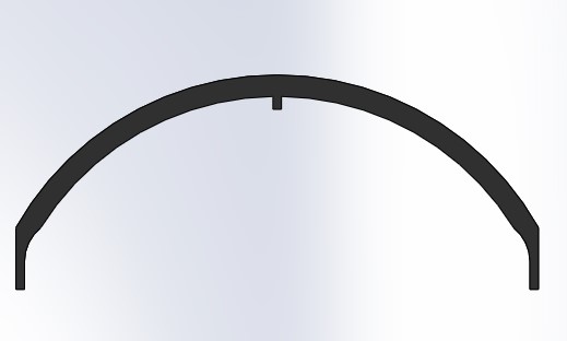
Figure 3: Clutch Sliding shoe
Shoe Support: Such a rigid base was modelled as a gray cast iron shoe support to keep the shoe in place and distribute the stress evenly.
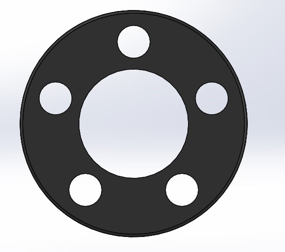
Figure 4: Clutch Housing
Shoe Support Holder: This malleable cast iron component was created to secure the shoe support and yet stay malleable enough to accommodate some thermal expansion.
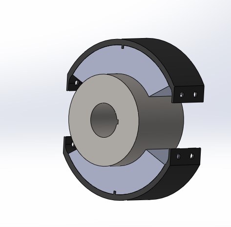
Figure 5: Centrifugal Clutch
Support Plate: The alloy steel support plate was modelled as a base which acts as a sturdy base for attaching the assembly (Fu et al.2023).
All of these were put together in a CAD environment, and precise alignment and various interference checks were made.
Material Selection
The materials were chosen based on their mechanical and thermal properties:
Shaft: Stainless steel for strength, corrosion resistance, and durability under rotational stress.
Shoe: High friction coefficient, wear resistance and thermal stability during engagement; therefore ceramic.
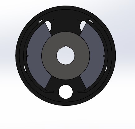
Figure 6: Clutch Assembley
Shoe Support: For its excellent (large) compressive strength and vibration damping, in gray cast iron.
Shoe Support Holder: For its toughness and capability of small deformations (Fu et al.2021).
Support Plate: Alloy steel for its high tensile strength and ability to withstand dynamic loads.
These choices assure operational reliability under actual operating conditions.
Motion Analysis
The performance of the centrifugal clutch under operational conditions was motion analysis to assess its engagement mechanism. Real-world rotational dynamics were simulated with CAD-integrated simulation tools.
Process and Input Parameters
Started with the input power from the engine, which is 1000 RPM, and began the analysis. The clutch shoes were supported to be moved radially outward through centrifugal force as the shaft rotated.
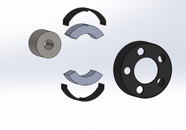
Figure 7: Clutch assembly Exploded view
These results are tied to the definition of the design, including the clutch's geometry and material properties. The engagement was simulated as the shoes went out by friction between the shoes as well as the drum. The following parameters were determined; The linear velocity of the clutch shoes near the drum surface (Chen et al.2022).
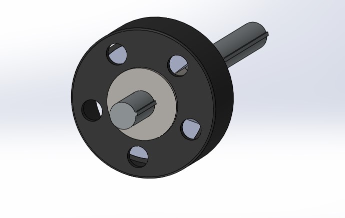
Figure 8: Clutch assembly with power shaft
Results
Linear Velocity: When the shoes rotated at a rate of 1000 RPMs expected to be engaged.
Radial Displacement: The shoes simulated an outward motion slowly, which was evidence of proper action of the clutch.
Contact Points: Non-wearable contact between the shoe and the drum was noted and the analysis also pointed to the power transfer efficiency.
The engagement process was graphed using linear velocity to time and radial displacement.
Validation of Clutch Engagement
Utilizing the motion analysis, the clutch functionality was validated; that engagement occurred at a controlled rate neither excessively locking nor slipping (Hamrangsekachaee et al.2023). The analysis also ascertained that the shoes were indeed properly coupled to the drum for efficient power transfer. These results confirm that the clutch design provides smooth engagement and safe operation as required in the design criteria, thus guaranteeing acceptable performance of the clutch in the real environment.
Finite Element Analysis (FEA)
FEA Setup
The performance and safety of the clutch shoe under maximum load conditions were assessed by performing Finite Element Analysis (FEA). Since the highest stress and strain is in the clutch shoe.
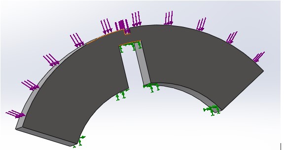
Figure 9: Clutch shoe fixed support with load directions
Carefully boundary conditions were defined in a way that reproduced real-world constraints. Constraints imposed by the assembly were simulated by fixing the shoe at the points of contact with a support holder. For the frictional surface of the shoe, a 50 N force is applied to engage the shoe with the drum at peak operating conditions (Milenković et al. 2022).
By incorporating accurate material properties of the ceramic shoe, realistic deformation and stress predictions were confirmed. The shoe was notched at critical points like edges and corners and then a fine mesh was applied to the shoe to capture detailed stress and strain distribution at critical points.
Results and Interpretation
The FEA produced the following results:

Figure 10: Clutch shoe stress
Maximum Stress: 3.111e+05 N/m², existing at the contact edges at which the force application and boundary constraints converge.
Minimum Stress: 7.910e+02 N/m² of minimal deformation away from the load has been found.
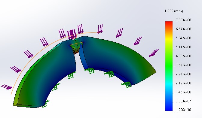
Figure 11: Clutch shoe displacement
Maximum Displacement: 7.303e-06 mm displacement of the shoe under load gave rise.
Minimum Displacement: 1.000e-30 mm, at the fixed support points.
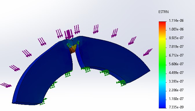
Figure 12: Clutch shoe strain
Maximum Strain: For the material's response to applied stress, it indicates a value, of 1.114e-06.
Minimum Strain: 7.335e-09, found in less stressed regions.
These results were visualized by plotting stress, strain and displacement. The stress plot indicated concentration zones at the contact edges of the shoe and the displacement plot showed the uniformity of the shoe's outwards motion under load.
Implications
The results show that the stress and strain are well below the ceramic material's yield strength, confirming the structural integrity and safety of the shoe in operation (Cera et al.2025). Validation for the robustness and alignment of the design is found in the minimal displacement and strain resulting from consistent engagement without deformation.
These results indicate that the clutch shoe will endure operating forces without failure and will meet basic safety and performance requirements. Additionally, through this FEA, the reliability of the design under peak load conditions is validated.
Discussion
Comparison with Standard Industrial Clutches
The design follows the industrial centrifugal clutch performance and material requirements quite closely. This design recommendation uses ceramic shoes for wear resistance and thermal stability while Industrial design uses a strong material such as cast iron and alloy steel for durability. Besides this, this clutch is also designed in a modular manner, the assembly or disassembly of which is very easy, thus fitting the characteristics of most industrial clutches.
The engagement RPM and motion analysis results provide gradual engagement as do clutches in small engines, which is a very smooth progression. FEA shows that the maximum stress and strain levels from the design are within safe limits and thus the design is reliable under operational loads.
Performance under Real-World Conditions
It is designed to engage at an RPM of 1000 RPM and provide no-slip transmission of power. The stainless steel shaft means it will last and the ceramic shoe provides high friction and excellent power transfer. Support structures use malleable and gray cast iron for increased durability and stability of the assembly. Safe and reliable operation is expected under normal and peak load conditions.
Areas for Improvement
While the current design meets safety and performance standards, there are opportunities for optimization:
- Material Testing: Further durability and reduced weight may be gained from experimentation with alternate materials for the shoes, such as composite materials (Gomez et al.2022).
- Heat Dissipation: The approach found adding ventilation features to the drum could improve heat dissipation during longer periods of use and thereby reduce thermal stress on the shoes.
- Dynamic Simulation: With further simulations at various RPMs and loads, additional insights regarding clutch performance can result.
Cost Efficiency: Affordable materials for non-critical parts of the product can enhance manufacturing without extending its poor performance.
Conclusion
The centrifugal clutch was developed based on the need for the clutch for the GX100 engine which was designed, modeled and analyzed for the engine. Motion analysis reveals the mechanical Coupling work at 1000 RPM. From FEA results maximum stress and strain values calculated were within the safe limits as proved the strength and durability designed for this component.
Functionality and reliability under utilisation were achieved due to effective materialization whereby ceramic was used for the shoe while the shaft was made of stainless steel.
Through the adoption of CAD and simulation tools in this study, it demonstrates how engineering design problems can be solved. The clutch is appropriate in this case, and the focus is application on material selection as well as heat elimination.
Reference List
Journals
- Cao, Z., Yang, X., Zhu, X. and Xia, Y., 2024. Optimal design and experimental study of comb-type disc magnetorheological brake. Measurement, 229, p.114458.
- Cera, M., Cirelli, M., Paoli, G. and Valentini, P.P., 2025. Comprehensive dynamic model of a full transmission driveline with nonlinear centrifugal damper. Nonlinear Dynamics, 113(4), pp.3001-3033.
- Chen, J., Bao, B., Liu, J., Wu, Y. and Wang, Q., 2022. Pendulum Energy Harvesters: A Review. Energies 2022, 15, 8674 [online]
- Fu, C., Lu, J., Ge, W., Tan, C. and Li, B., 2023. A Review of Electromagnetic Energy Regenerative Suspension System & Key Technologies. Cmes-Computer Modeling in Engineering & Sciences, 135(3).
- Fu, J., Xie, G., Ji, C., Wang, W., Zhou, Y., Zhang, G., Zha, X. and Abdeen, M.A., 2021. Study on the distribution pattern of threshed mixture by drum-shape bar-tooth longitudinal axial flow threshing and separating device. Agriculture, 11(8), p.756.
- Gomez, E.R., Sjöstrand, J., Kari, L. and Arteaga, I.L., 2022. Torsional vibrations in heavy-truck powertrains with flywheel attached centrifugal pendulum vibration absorbers. Mechanism and Machine Theory, 167, p.104547.
- Hamrangsekachaee, M., Wen, K., Bencherif, S.A. and Ebong, E.E., 2023. Atherosclerosis and endothelial mechanotransduction: current knowledge and models for future research. American Journal of Physiology-Cell Physiology, 324(2), pp.C488-C504.
- Li, D., Bakar, S.A.A., Hussein, M., Wei, J., Tang, J. and He, Y., 2024. MODELLING AND SIMULATION OF AN MR BRAKE BASED ON TORQUE COMPENSATION. Journal of Transport System Engineering, pp.60-72.
- Milenković, B., Jovanović, Đ. and Krstić, M., 2022. An application of Dingo Optimization Algorithm (DOA) for solving continuous engineering problems. FME Transactions, 50(2), pp.331-338.
- Ni, C., 2024. Design and modelling of the clean energy router with advanced adiabatic compressed air energy storage system (Doctoral dissertation, University of Birmingham).
- Panchal, D., Patel, B. and Gohil, H., 2023. Experimental Investigation on Performance Characteristics of Dry Centrifugal Clutch with Grooved Friction Liners. International Journal of Automotive and Mechanical Engineering, 20(1), pp.10152-10164.
- Wang, W., Liu, Y., Bai, F. and Xue, G., 2021. Capture power prediction of the frustum of a cone shaped floating body based on BP neural network. Journal of Marine Science and Engineering, 9(6), p.656.