Object Oriented Systems Development Assignment Example
A Comprehensive Example Showcasing Key Concepts and Techniques in Object-Oriented Systems Development
- 92650+ Project Delivered
- 1500+ Experts 24x7 Online Help
- No AI Generated Content
Introduction - Object Oriented Systems Development Assignment
UML case diagram is basically used to demonstrate the working procedure through some figures. Each of the figures are having their individual meaning to make any kind of project. So in that current study they are asking for a working procedure where a student will be the admin and also there will be some user of the application. So a simple library management system can be figured in the current study. There will be some users where they will be able to make them registered in the application and the admin can check the details of those users. Each and every requirement will be fulfilled through these diagrams.
Experience the difference with premium Assignment Writing Help from New Assignment Help. Our commitment to excellence ensures you receive thoroughly researched, properly formatted assignments that help boost your grades.
1.UML Use Case Diagram.

Figure 1: Use case diagram
(Source: draw.io)
In the figure shown above a use case diagram has been created in draw.io platform in order to show the use case of the library. The actors are generated to make it easy to understand there is an admin and a user. Admin can make all the changes and also can add and delete the users and the users can only search for their required books and make their account and can operate.
2.List of Nouns from the Requirements Document and classes
To say about the list of documents it can be said that to run this application an admin section and obviously the admin will be present in the case study (Lor, 2018). Now to be the admin of this application the main requirement is the admin should have his or her proper id to operate the application and with thenname, contact and the address. These are the basic requirements of the admin.
Such user registration and authentication functionalities are commonly implemented using server-side technologies, making PHP one of the most widely used programming languages for developing database-driven web applications. For students struggling with these concepts, our PHP Assignment Help UK service provides guidance on developing secure and scalable web applications.
3. UML Class Diagram.
Class diagrams are commonly used for modelling technique of a software software's permanent display, as well as thorough modelling of translation models of actual software programs. A class diagram is commonly used while creating or building software products. They are indeed employed with data modelling. It is used to depict classes, interactions between them, interfaces, associations, and so on. A class in a class diagram is essentially an object's template. It simply specifies and illustrates the many sorts of items in the structure, as well as the multiple kinds of relationships which exist amongst those.
4. Identify Class Attributes.
The main attributes are of this library management system are listed below:
For the attributes of library management system: usertype, username and the password.
For user attribute: name and the ID
For the librarian attributes: name, along with the id, password and the final one is SearchString.
For the book attributes: Title of the book, author name, publication etc.
For account attribute: fine amount, no return books, no reserved books and no borrowed books these can be selected for the account attribute.
For the database of the library attributes list of books might be the factor.
Dept can be selected for the staff class attribute with the class in student class attribute.
5.UML Activity and state diagram
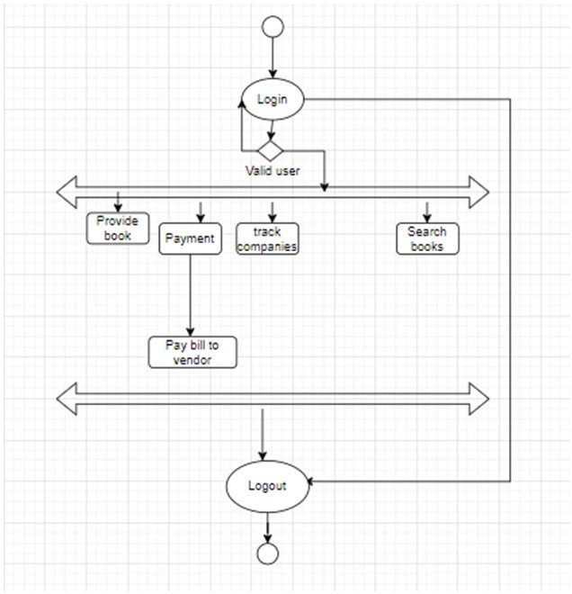
Figure: Activity and state diagram
(Source: draw.io)
The above shown figure is the activity diagram that has been implemented by the designers. This is the one of a UML diagram which shows the behaviour of the application and also its users. This activity diagram in the library management system is like a shape and the arrows and interaction in between the user and the system. Let it explain its meaning and implications to the designers and they will have a good knowledge of it. The Library management system offers a feature that can be of great use to the libraries of any school or university. To demonstrate the process and how it will contact its users, users must design an activity diagram for the Library Management System.One will be willing to show the flow of processes and know what the exchanges between systems and also its consumers should have used the activity diagram. By viewing the activity diagram, all customers and consumers will indeed be advised on how to utilise the library management system. That really is the significance of something like the Library Management System.
6.Identify Class Operations.
In the current statement we have shown only the four class attributes to make it understandable. Several classes can be selected to make a class operation like for the system class of the main library management (Rathor et al. 2020). It is used to manage all the operations in the application of the library management system. This is basically the central part of the designed software.
Second part is the user class it uses to manage all the operations for use. Next part is the librarian class that manages all the operations of the librarians. And the other corresponding classes are the book class, user class and so on.
7.UML Communication Diagram.
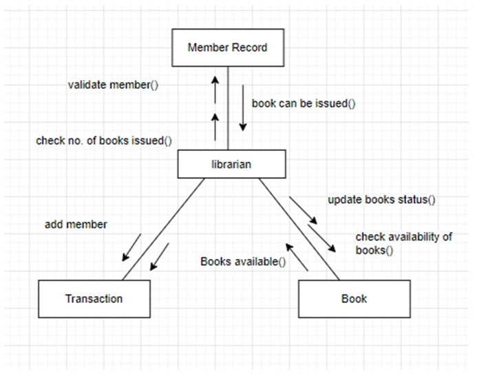
Figure: communication diagram
(Source: draw.io)
Above figure is the communication diagram that was also created in the draw.io platform to be understandable (Wong and Chan, 2018). A communication diagram provides the very same details as a sequence, however a sequence diagram focuses on the frequency and chronology of occurrences, whereas a communication diagram highlights the communication transferred amongst elements in a system. Visualisations frequently fall short of providing the "complete picture. “Communication diagrams have comparable capabilities to graphical representations, but they provide a greater comprehension about how components communicate with each other instead of focusing exclusively on the order of events. They may be an invaluable resource for corporations, organisations, and engineers that need to perceive and comprehend the practical communication inside one software.
8. Sequence diagram
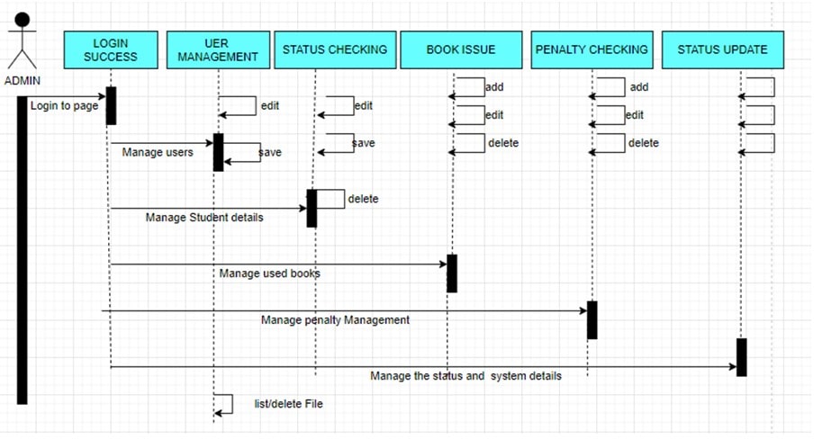
Figure: Sequence diagram
(Source: draw.io)
Sequence diagrams are also a kind of universal modelling language diagram. They are often used to demonstrate how components in a system interact with each other throughout the duration. A sequence diagram assists a system designer in visualising and comprehending the order where such components interact. This can help uncover possible issues and optimise how this all operates (kparobore and Akparobore, 2019). The sequence diagram depicts the sequence of events in the system spanning top to bottom. The items are depicted as labelled triangles just at top and bottom of the picture, with a lifeline descending the whole duration of the image. Relationships amongst items are represented by horizontally arrows pointing left or right. These are instructions that are exchanged here between components.
Conclusion
As it has been discussed before starting of the project that a library management system is going to be created, like the same agenda all the diagrams have been created to understand about the entire project. Coursework has been provided from the university side to make a generic topic. So the developers or the students have created a simple demonstration of a library management system with all its attributes and required agendas. In the very beginning of the coursework an introduction has been provided like what is going to be implemented throughout the research. So like the same procedure draw.io platform has been selected to make all the drawing parts of the requirements. At the initial stage a very simple use case diagram has been shown to make a small demonstration of the entire work that is going to be done. And after the first part of the use case diagram, students have created the UML class diagram and made a list of those classes that might be required to make the software. And the figure 2 shows the class attributes and the class diagrams. And slowly after making a scene of the attributes and after getting all the properties the remaining parts of the coursework have been completed by the developers.
Reference list
Journals
Akparobore, D. and Akparobore, D.O., 2019. Toward Improving Library Automation in Delta State University Library, Abraka. Library Philosophy and Practice (e-journal), 2267.
Dash, S., 2019. Google classroom as a learning management system to teach biochemistry in a medical school. Biochemistry and Molecular Biology Education, 47(4), pp.404-407.
Lin, N.Y., Ramsey, R.R., Miller, J.L., McDowell, K.M., Zhang, N., Hommel, K. and Guilbert, T.W., 2020. Telehealth delivery of adherence and medication management system improves outcomes in inner‐city children with asthma. Pediatric Pulmonology, 55(4), pp.858-865.
Lor, P.J., 2018. Democracy, information, and libraries in a time of post-truth discourse. Library Management.
Martzoukou, K., 2020. Academic libraries in COVID-19: a renewed mission for digital literacy. Library management.
Rathor, S.K. and Saxena, D., 2020. Energy management system for smart grid: An overview and key issues. International Journal of Energy Research, 44(6), pp.4067-4109.
Wong, G.K.W. and Chan, D.L., 2018. Adaptive leadership in academic libraries. Library Management.