3d model Structure Autodesk Revit Assignment Sample
Learn to create a detailed 3D model of the structure using Autodesk Revit assignment sample to enhance design & presentation skills.
- 92650+ Project Delivered
- 1500+ Experts 24x7 Online Help
- No AI Generated Content
Introduction of 3d model of the structure using Autodesk Revit Assignment
The given task for the activity was to create, architect, and build a bridge out of Bucatini pasta, while considering basic fundamental civil engineering concepts in an effort to meet required load-carrying capacity while aiming to achieve minimum weight. The structure is for a gap of 750 mm while the difference in height of the two support is 90 mm the structure supports a point load of 80N placed at a distance of 200mm from one of the support. AutoCAD and Autodesk Revit were utilised to build the design that would allow for an A3 drawing with clear view and further detailed plan and construction with consideration of all dimensions and materials used. Here, necessary actions are described in the process of the task implementation, from modelling to the output.
Your university guidelines are our blueprint. Let New Assignment Help craft your perfect paper with tailored assignment help.
Procedure
Autodesk Revit setting
An additional project was created in Autodesk Revit; this project was set up with a structural template so the correct tools were available for the bridge construction. Nine drawing units were set up to metric, and the workspace was arranged to provide the 750 mm span needed; one support was positioned 90mm above the other.
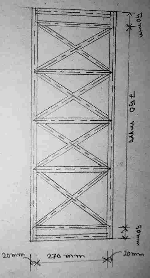
Figure 1: Top view of Bridge
Creating the Bridge Span
The main idea behind the design of the bridge was done by arranging a beam tool in the Revit. To replicate the height difference of the supports I placed a 750 mm long beam horizontally with two of its ends touching the corresponding supports. The material properties for the Bucatini pasta were introduced applying a material with a desired weight and structural load-carrying capability in Revit.
Modeling the Supports
It was necessary to instal little support columns at both ends of the bridge. New left support was developed at base level and the right support was increased by 90 mm as per the requirement. By employing the family editor, the support structures were adapted to the peculiarities of the presented project. These supports were intended to support the loads placed at the particular positions.
Adding Load Points
Using the structural features or Revit analysis, an 80N point load was applied to a beam at 200 mm from one of the support points. This provided a close to real life loads distribution on the beam to understand the forces for aggresive loads acting on the structure. The capacity of the bridge was also made to accommodate this load for failure and at the same time make the structure light by optimising the dimensions of the beams and the properties of the materials used.
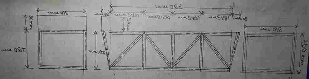
Figure 2: Elevation with Sectional view of Bridge
Creating the Views
- Several views were generated to provide a comprehensive representation of the bridge structure:
- Finally, a plan view drawn was made to display the proposed whole length of the bridge and distributions of the beams and pillars.
- Plan view was prepared as a section view sectioning the bridge longitudinally to reveal details of internal structures.
- Connexion detail view was created as shown below to depict how the beams were connected to the supports clearly for construct.
- A side elevation was created also in order to exploit the difference in height of the supports and obtain an overall view of the side of the structure.
- Every dimension that could be laid down on the drawing was well outlined, including the span length, height difference, and load point of application.
![Bottom Plan]()
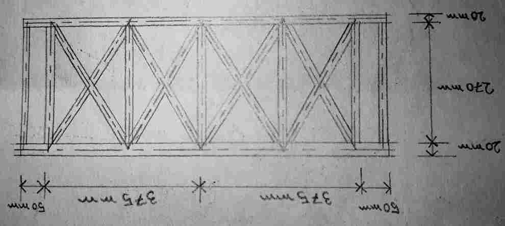
Figure 3: Bottom Plan
Title Block and Annotation
A title block was included into the A3 drawing format; this included; title of the project, date and student data . Some notes and comments were made to emphasise various parts of the bridge; the material characteristics, reinforcement loads, etc. The last drawing was done deliberately in such a way that a builder could build the structure following the descriptions given.
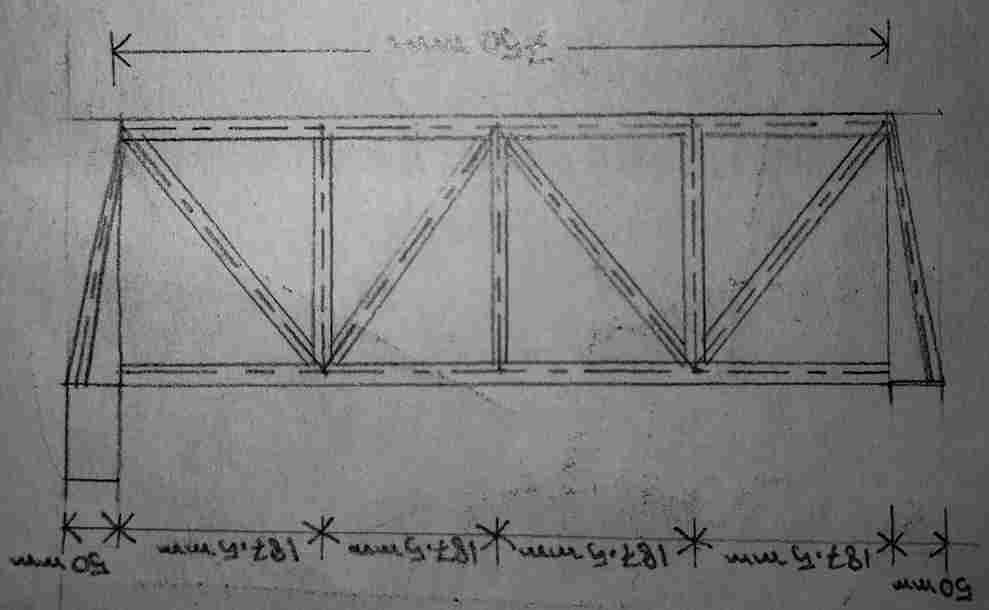
Figure 4: Inverted Bridge
Exporting the Files
As soon as the model and drawing were completed, the A3 drawing was converted to a PDF to conform with the submission specifications. Furthermore, the actual design was created in the Revit 3D model and views along with the Revit file (.rvt) were saved and ready for submission. This way a detailed drawing and a digital model of the structure are available for reference and creation of subsequent models.
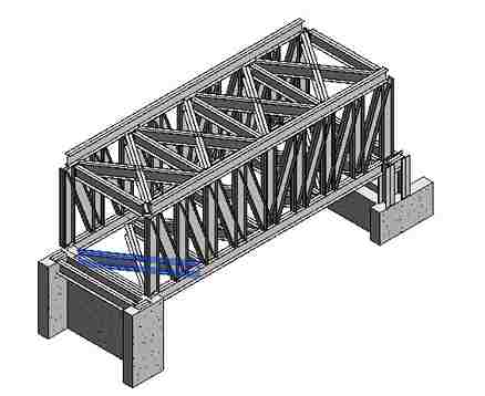
Figure 5: 3D model of the Bridge
Conclusion
The requirement given in the brief for bridge design and modelling were satisfactorily fulfilled in this project employing Autodesk Revit. The structure was designed to stand between two steel plates with the gap of 750 mm, to fit the 90 mm difference in height and withstand an 80N load at a specific point. In the final A3 drawing, plan, section, connexion detail and elevation are created so that all information needed to build the structure can be drawn from it. The Revit file was created together with the PDF drawing which in its turn indicates the possibility of successful implementation of the methods and approaches described in the course of the theoretical analysis with the help of practical work.
Reference List
Journals
- Akanbi, T. and Zhang, J., 2022. Semi-automated generation of 3D bridge models from 2D PDF bridge drawings. In;Construction Research Congress 2022;(pp. 1347-1354).
- Pratama, S.T.D.F., Rifai, A.I., Saputra, A.J. and Prasetijo, J., 2024. A Bridge Planning Simulation with Building Information Model: Steel Frame Structure.;Journal Research of Social Science, Economics, and Management,;4(2), pp.310-317.
- Trochymiak, W., Krygier, A., Stachura, M. and Jaworski, J., 2023. The BIM 5D model of the bridge built using the incremental launching method.;Archives of Civil Engineering,;69(3).