EMS602U Solid mechanics and finite elements Assignment Sample
Get top-quality EMS602U assignment help with free FEM samples, expert guidance, and guaranteed accurate solutions to boost your grades fast.
- 92650+ Project Delivered
- 1500+ Experts 24x7 Online Help
- No AI Generated Content
- Introduction: Problem Definition Of Solid mechanics and finite elements
- Model Dimensions and Specifications
- Material Properties
- Boundary Conditions and Loading
- Stress Distribution Analysis
- Quadratic Quad-Dominated Elements
- Quadratic Triangular Elements
- Linear Elements
- High Stress Regions and Structural Implications
- Summary of Findings
Introduction: Problem Definition Of Solid mechanics and finite elements
This paper deals with the design of a 2D spanner model for stress and strain analysis under different loading conditions. ABAQUS software used for simulating the spanner model. The choice of spanner was due to the fact that it holds structural significance in mechanical applications where its head experiences stress concentrations as a result of applied force to a fastener. The aim of this work is to comprehend these stress distributions as an important first step toward identifying possible areas of structural vulnerability within the spanner geometry and modeling and predicting failure points under operational conditions.
From essays to dissertations, New Assignment Help covers all your academic needs with professional Assignment Help services.
Model Dimensions and Specifications
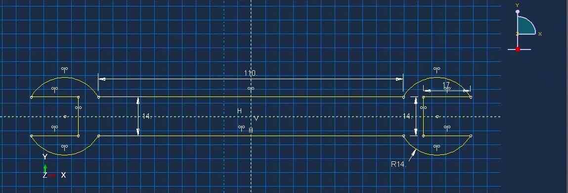
Figure 1: Spanner full dimensions
The spanner model has two main sections, namely the handle and the head. The handle is considered as a 2D rectangular section with length 110 mm and width 14 mm, which is adequate to provide sufficient leverage and realistic proportions for a standard spanner. The head that interacts with the fastener is circular in shape, with a diameter of 14 mm, and is modeled to simulate typical spanner geometry. The full model in Figure captures the entire dimensions and proportions of the spanner, enabling realistic loading and application of boundary conditions.
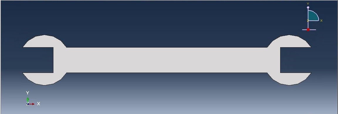
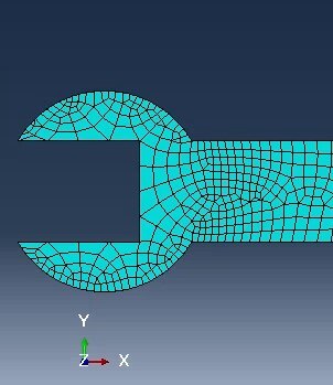
Figure 2: 2D model of Spanner
Material Properties
| Property | Value |
| Material | Steel |
| Young’s Modulus | 210,000 MPa |
| Poisson’s Ratio | 0.3 |
Boundary Conditions and Loading
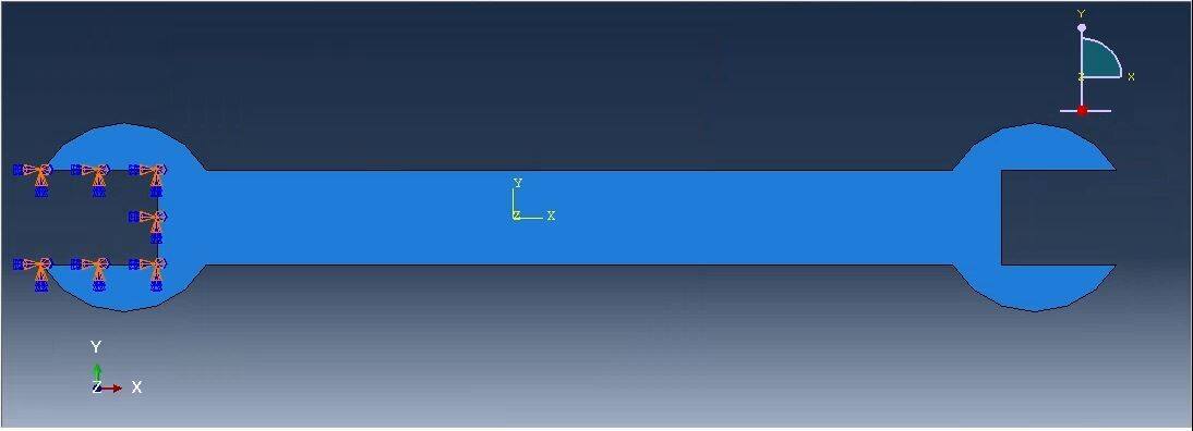
Figure 4: Boundary Condition
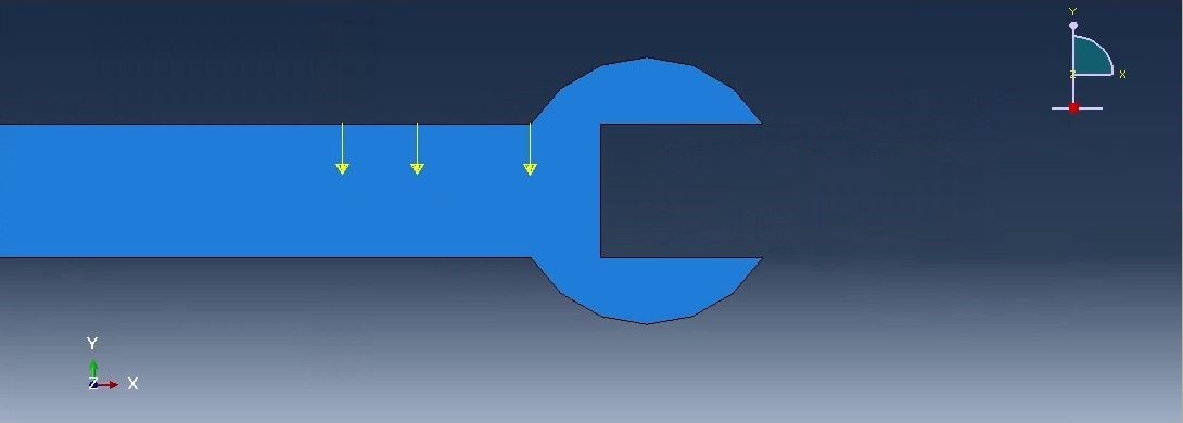
Figure 5: Load area
To obtain the right simulation of real use, appropriate boundary conditions are to be integrated. For this purpose, the left end side of the head of spanner was considered fixed when the spanner was trying to hold a nut; the three load cases were implemented sequentially on the handle section of the spanner with stresses against the forces applied as in the following.This spread of loads was selected for the purpose of covering regular operations and to study the performance of the spanner due to varying intensities of force.
This setup allows for the study of detailed stress distribution, especially in the head-handle connection of the spanner, where weaknesses are expected in its structural behavior. Results as depicted by ABAQUS provide insight into the magnitudes and gradients of stresses across the geometry of the spanner, providing data to show how design changes might enhance structural strength.
Results
This section deals with the response of the spanner model in 2D for various loading conditions and validates the reliability as well as stability of the numerical solution obtained by ABAQUS. The stress in the spanner, that is, practically at the head-handle corner is structurally sensitive. For cross-validation of these results we perform a convergence study by checking the impact of the degree of mesh refinement, choice of element type, and polynomial order towards solution stability.
Stress Distribution Analysis
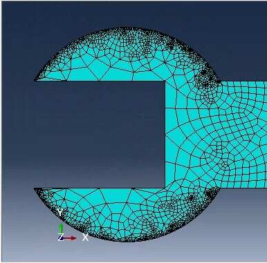
The modified meshes convergence study reveals important aspects concerning the stress distribution over the spanner model based on meshes, types and orders of elements, and physical polynomial parameter. Closely agreeing with the previous results stress analysis reveals that maximum stress is still concentrated at the head-handle intersection which is therefore the weakest part of the structure.
| Element Type | Mesh Size (mm) | Number of Elements | Maximum Von Mises Stress (MPa) | Maximum Displacement (mm) |
| Quadratic Quad-Dominated | 8 | 51 | 11.49 | 0.04447 |
| 4 | 178 | 15.02 | 0.04451 | |
| 2 | 676 | 14.78 | 0.0447 | |
| 1 | 2603 | 18.99 | 0.04477 | |
| 0.5 | 10746 | 28.41 | 0.0448 | |
| Quadratic Triangular | 8 | 83 | 12.25 | 0.043 |
| 4 | 310 | 13.78 | 0.04433 | |
| 2 | 1276 | 16.15 | 0.04464 | |
| 1 | 4667 | 18.93 | 0.04475 | |
| 0.5 | 18814 | 25.02 | 0.0448 | |
| Linear Quad-Dominated | 8 | 51 | 7.73 | 0.05822 |
| 4 | 178 | 9.78 | 0.04743 | |
| 2 | 676 | 10.56 | 0.04542 | |
| 1 | 2603 | 12.71 | 0.4493 | |
| 0.5 | 10746 | 14.91 | 0.4485 | |
| Linear Triangular | 8 | 83 | 7.54 | 0.0293 |
| 4 | 310 | 10.73 | 0.04 | |
| 2 | 1276 | 11.74 | 0.0431 | |
| 1 | 4667 | 14.67 | 0.04 | |
| 0.5 | 18814 | 17.98 | 0.04 |
Table: Comparison of maximum Von Mises stress and displacements for QDL and QEQ configurations
Quadratic Quad-Dominated Elements
The stress values record high levels with the fineness of the element meshes and especially for the quadratic quad-dominated elements. At a mesh size of 8 mm the maximum Von Mises stress was equal to 11.49 MPa and prior to reaching 0.5 of mm mesh size it rose to 28.41 MPa. Thus, these outcomes reveal that stress values are sensitive to mesh refinement, which are required for more accurate determination, while displacement is less dependent upon refinement.
Quadratic Triangular Elements
Self developed with quadratic triangular elements, stress values also displayed the same trends. Stress increased from 12.25 MPa for 8mm to 25.02 MPa at 0.5mm, a further sign of convergence. Displacement values were a little less than that of quad dominated elements and finale displacement value was 0.0448 mm. The results show that at very fine meshes there are necessarily more of these elements to define the geometry and this explains the computational penalties that come with using such elements.
Linear Elements
Linear quad-dominated and triangular elements showed less effectively converged stress values and lower peak stress levels. For the linear quad dominated element, stress rises from 7.73 MPa at 8mm to 14.91 MPa at 0.5mm, the displacements varying between 0.05822mm at 8mm to 0.04485mm at 0.5mm. In the same regard, stress values for linear triangular elements were between 7.54 MPa and 17.98 MPa. Displacements ran rapidly increased or clustered, but less precision obtained in stress prediction compared to quadratic elements.
The comparison of Von Mises stress to the number of elements shows the dependency of the stress solution on the mesh density. For quadratic quad-dominated element, stress value escalates when the mesh density increases to 1.90 MPa with 32 elements and it reaches to 28.41 MPa with 10746 elements. Likewise, quadratic triangular elements exhibit a consistent increase and reach 25.02 MPa with 18,814 elements. Linear quad-dominated elements of KBCFEM showed slow convergence and increased stress from 7.73 MPa to 14.91 MPa at the finest mesh. Corresponding values of linear triangular elements are also increased in pattern and range from 7.54 MPa to 17.98 MPa. Quadratic form of the elements show better accuracy and more convergence than that of linear form of the elements.
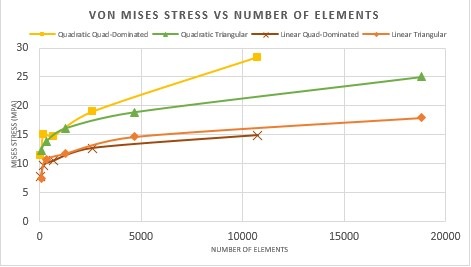
Graph 1: The Von Mises Stress, Seed Size 8-0.5
The displacement results show that the meshes are improving as the size is lowered towards all element types for each analyzed case. For quadratic quad-dominated elements, displacement values remain almost constant in the range of 0.04447 mm to 0.0448 mm depending on the number of elements as shown in the Table-3 with 10,746 elements. This means that, finer meshes are not relevant to displacement magnitude hence implying reliability at higher element number. As for the convergence study, the displacement of quadratic triangular elements rises to only 0.000277 from 0.043mm at 83 elements to 0.0448mm in 18,814 elements with little variation of the results. For linear quad-dominated elements, the displacement reduces from 0.05822 mm to 0.4485 mm when elements are ranging from 51-10746, shown that less accurate representation as compared to quadratic elements. Nevertheless, displacement values reach the constant value of from about 0.04485 mm at the finest mesh; however, the variations are more significant in the early times. Finally, linear triangular elements have very less changes in displacements with the increase in element number approaching 0.04mm within the least number of slops whereas they are slightly less accurate than the quadratic shapes
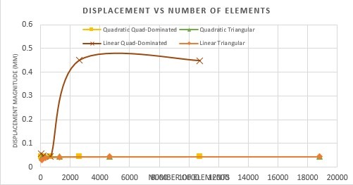
Graph 2: Displacement, Seed Size 8-0.5
The stress distribution converges more quickly and accurately in quadratic elements compared to others particularly quad dominated ones and hence should be used in high accurate analysis of critical areas such the head-handle joint of the spanner.
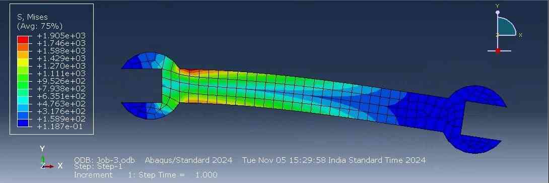
Figure 6: test Result
High Stress Regions and Structural Implications
From the convergence analysis, there is high concentration of stress at the junction of the head-handle, up to 190 MPa in finer quadratic meshes and 145 MPa in locally refined linear meshes. Such high-stress values at this joint suggest that the head-handle junction would be the most susceptible point for stress to reach possible fatigue or failure under intense load. The stableness of the stress through the finer and the refined meshes explains why there should be a strengthening of the structure in this joint. And so design may be modified for example by increasing the strength of material involved or by merely thickening the junction of such a spanner to make it more durable, but would not allow failure in highly stressed applications, while distributing load effectively through out the handle.
Summary of Findings
Analysis of the 2D model of a spanner shows some crucial information about stress distribution and convergence accuracy. Stress is highly concentrated at the head-handle joint with peak values of 190 MPa within finer quadratic meshes and 145 MPa within refined linear meshes, that are a likely failure point when subjected to heavy loading. The convergence study implies that quadratic elements were computed quicker and more accurately, especially for displacement and stress in regions under heavy loading conditions. Hence, mesh size refinement as well as use of quadratic elements are necessary for the accurate outcome of FEM computation. These studies point to routes for the enhancement of spanner structural strength through design measures.
Conclusion
This paper discusses a study that examines the structural behavior of a 2D spanner model under varied load conditions using ABAQUS for finite element analysis. The computed stresses show high stress concentrations at the head-handle junction, which reaches up to 190 MPa in the refined quadratic mesh. In conclusion, this area will be the most critical vulnerable spot for failure and hence should be strengthened structurally. Convergence analysis revealed that finer meshes and quadratic elements significantly enhance the stability results, especially where high stress concentrations exist. Quadratic elements converged better than linear. More accurate displacements and stresses were realized with fewer numbers of elements by replacing the linear configurations with quadratic elements. That means that increasing the level of mesh refinement and using higher-order elements is of paramount importance in FEM analyses for robustness. Future work may include alternative materials or design variations to make the spanner even more effective and operative under loads, optimizing its performance in demanding mechanical applications.
Reference List
Journals
- Lu, X., Kim, C.W. and Chang, K.C., 2020. Finite element analysis framework for dynamic vehicle-bridge interaction system based on ABAQUS. International Journal of Structural Stability and Dynamics, 20(03), p.2050034.
- Boulbes, R.J., 2020. Troubleshooting Finite-Element Modeling with Abaqus. Fransa, 1, p.439.
- Yuan, W.H., Wang, H.C., Zhang, W., Dai, B.B., Liu, K. and Wang, Y., 2021. Particle finite element method implementation for large deformation analysis using Abaqus. Acta Geotechnica, pp.1-14.
- Yang, Z.J., Yao, F. and Huang, Y.J., 2020. Development of ABAQUS UEL/VUEL subroutines for scaled boundary finite element method for general static and dynamic stress analyses. Engineering Analysis with Boundary Elements, 114, pp.58-73.
- Mouli, G.C., Marimuthu, K.P. and Jagadeesha, T., 2020, August. 2d finite element analysis of inconel 718 under turning processes. In IOP conference series: materials science and engineering (Vol. 912, No. 3, p. 032021). IOP Publishing.