CHEM1136 Final Year Design Project Assignment Sample
Complete design project sample including detailed distillation calculations, equipment specifications, piping design, control strategies, startup procedures, and capital cost assessment.
- 92650+ Project Delivered
- 1500+ Experts 24x7 Online Help
- No AI Generated Content
- 1. Introduction Of CHEM1136 Final Year Design Project Assignment
- 1.1 Design Objective
- 1.2 Process Overview
- 1.3 Overall Mass & Energy Balance
- 1.3.1 Mass Balance
- 1.3.2 Energy Balance
- 2 Detailed design
- 2.1 Design Node Overview
- 2.1.1 Function of the Distillation Column
- 2.1.2 Process Flow Diagram (PFD)
- 2.1.3 Detailed Mass and Energy Balance
- 2.2 Detailed Design calculations
- 2.2.1 Distillation column calculations
- Determination of Key Component Recoveries
- Calculation of Minimum Number of Trays Using Fenske Equation
- Reflux Ratio Determination Using Erbar-Maddox Correlation
- Adjustment for Tray Efficiency
- 5.2.2 Column Sizing and Tray Design
- Physical Properties Calculation
- Column Diameter Calculation
- Liquid Flow Pattern Assessment
- Provisional Plate Design and Hydraulic Checks
- Perforated Area and Hole Calculations
- 2.2.3 Engineering Drawings
- General Arrangement Drawing (GA):
- Piping and Instrumentation Diagram (P&ID):
- Isometric Drawings:
- Tray Layout Drawings:
- Fabrication Drawings:
- 2.2.4 Pipe sizing/Diameter Calculations
- 2.2.5 Pump Design
- 2.2.6 Control Valve Design
- 3 Process specification
- 3.1 Overview of Node Equipment (Their Purpose)
- 3.2 Specification Sheets
- 3.3 Specification for Pump, Pipes, and Valves
- 4 Control strategy & specification
- 4.1 PID (Process Instrumentation Diagram)
- 4.2 Control Strategy
- 4.3 Startup / shutdown / emergency procedures
- 4.3.1 Startup Procedures
- 5. Hazards
- 5.2 Mitigation of Hazards
- 6 Economic evaluation
- 6.1 Capital Cost Assessment
- 7 Conclusions
- 7.1 Conclusion/Summary of Key Findings
1. Introduction Of CHEM1136 Final Year Design Project Assignment
1.1 Design Objective
This design project’s central aim is to design a distillation column appropriate to a diesel treatment plant from an initial basis, distilling down to a fine-detail design. The component will be gathered and held by the column on the basis of boiling points so that the process is reasonable and satisfactory. In the design, there will be a feed pump for supply of the fluid to the column and a control valve for the regulation of the flow rate. The objectives of the project setting is to achieve optimality in the separation equipment design given safety and operational considerations.
1.2 Process Overview
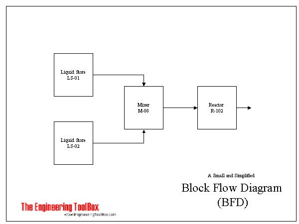
Figure 1: Block flow diagram
The distillation column is one of the key components in the diesel treatment plant and is specifically aimed at dividing a mixture of hydrocarbons into fractions by means of boiling points. This starts with the feed mixture being introduced in the column to undergo vapor-liquid equilibrium in several stages. This column works at normal pressure (1 ATM) and hence uses sieves which help in combination of the vapor as well as the liquid phases to facilitate efficiency in the separation process (Zhang et al., 2022). It varies within the column from about 161 °C to about 361 °C while the temperature of the reboiler, which is located at the lower section of the column, is about 350 °C; and the top section of the column is about 208 °C. This causes the separation process whereby the components with low density move to the least dense region that is at the top while the components with high density move to the high density region that is at the bottom. It contains three branching columns arranged in triangular form, of equal distance in temperature variation to accomplish separation of the mid-range fractions. This means the distillation process is controlled in a manner that will ensure maximum efficiency in the separation process. The rate of feed mixture is controlled through a feed pump and a control valve that ensures the flow of the mixture into the column is constant allowing for constant operation. The reboiler supplies the heat energy required for vaporising the liquid bottom product and at the top, the condenser cools the vapor for the condensation process thus allowing for the separation of the different fractions (Kong et al., 2023). The setting out target of the overall design of the process is to get maximum purity on the products in the most efficient manner using least energy and cost.
Assignment deadlines piling up? Let New Assignment Help ease your burden with expert Assignment Help in UK tailored for student success.
1.3 Overall Mass & Energy Balance
1.3.1 Mass Balance
The mass balance in a distillation column can be described as the overall mass flowing into the distillation column is the same as the overall mass flowing out of it. This entails monitoring the feed rates and the composition of its contents, the distillate, and the content of the bottom products. The composition and flow rate of feed mixture which contains a number of hydrocarbons, nitrogen and sulfur compounds are as follows. Measuring mass balances are then performed in order to allocate quantitatively each component in the bottom and distillate products to the required specifications (Quader et al., 2021). This ensures that the operation of this column is in the most efficient way for purposes of separation and quality of the products that are being determined.
1.3.2 Energy Balance
The energy accounting section in a distillation column determines the energy that is used and released and identifies it to the energy inflow and outflow. It Circulates heat to the reboiler to turn the liquid at the base of the column into vapor distillate and also takes heat from the condenser and condenses the vapor into the distillate. The energy balance determines the duties of the reboiler and the condenser based on the changes of enthalpy that occurs in the process of vaporization and condensing. It also considers heat losses so that the temperature gradient in the column is effective in the separation and minimal loss of energy is incurred (Finberg and Shiflett, 2021). The mass and energy balances respectively regulate the distillation along with the said process.
2 Detailed design
2.1 Design Node Overview
The distillation column structure entails several engineering and maths activities that are central in the fabrication of the column for the efficient and efficient performance without compromise on safety. It is one of the main parts of the diesel treatment plant labeled to break into barrel hydrocarbons in accordance with their boil point. There are several important stages of the design which are very important steps toward enhancing the separation efficiency and the overall stability of the equipment.
2.1.1 Function of the Distillation Column
Its main use is in the separation process of separating a mixture of the feed into several fractions of hydrocarbons. This is done by a process that includes numbers of stages where the components having higher equilibrium vapor pressure concentrate themselves in the vapor phase while the components which have low equilibrium vapor pressure concentrate in the liquid phase (Martínez et al., 2024). Its elements are calculated to provide a certain flow rate and concentration, so that the separation of the material in question is efficient for the specified feedstock. Also, the distillation column design needs to incorporate the feed surge volume and fluctuations in the feed composition and flow rates. It is fitted with control systems that have the capacity to vary the operating parameters of the column in real-time in a way that enhances the specific separation efficiency. This sliding feature is paramount in the establishment maintaining a quality product even in cases of upset conditions (Li et al., 2023). There are safety consideration in the design of the plant including pressure relief systems and emergency shutdown systems for safety measure purposes to safeguard people and equipments that are involved in the plant.
2.1.2 Process Flow Diagram (PFD)
This is illustrated in the process flow diagram (PFD) of the distillation column and the equipment incorporated in its design. EE shows the manner in which the feed mixture is fed to the column, the separation taking place in the column, as well as the distillate and bottoms products. It also indicates the function of some components of the PFD like the feed pump, control valve, reboiler and condenser (Stichlmair et al., 2021). Another useful aspect of this diagram is related to the fact that it provides an overview of the flow of the process alongside the input, processes, output, and feedback loops of one or multiple components of the system.
Moreover, the PFD is useful for pointing out the directions for analyzing more detailed issues of dislocation and inefficiency. The fundamental finite method of analyzing the flow of materials and energy across a system can then be applied to the design for better efficiency of separation and reduction of energy usage. It also assists in triggering of control strategies through providing clear relationship of the variable and the control element in the process (Cui et al., 2021). Such representation is important to convey when new operators are introduced onto the current process, and all qualification is being tested for an understanding of the process and control of the process.
2.1.3 Detailed Mass and Energy Balance
These involve the overall mass and energy balance as some of the key crucial aspects in designing the power plant. These calculations make it possible for the mass and energy at the inlet streams of a column to be equal to the mass and energy at outlet streams in order to obtain a steady-state operation (Waibel et al., 2023). The key processes that need to be modeled in the analysis include the mass flow rates of the feed, distillate, and bottom products. However, the mass and energy balance also has its worth as it helps make sense of the operational capacity of the column and of its inefficiencies. When this information is analyzed, engineers are able to determine the possibilities of improving the separation performance in different aspects such as energy usage. It also applies when determining types of changes that are most appropriate in help to create control strategies which are vital in sustaining the required operating conditions of the process as well as reacting to different changes in the process (Yusuf and Almomani, 2023). The mass and energy balance calculations need constant updates mainly because of fluctuation in feed composition, flow rates, and other parameters so as to achieve optimization of the unit and maintaining safety while operating the column.
2.2 Detailed Design calculations
2.2.1 Distillation column calculations
Initial Design Parameters
The conditions employed in the distillation column design are as follows:
Operating pressure: 1 atm (101.325 kPa)
Temperature range: 161-361°C
Bottom temperature: 350°C
Top temperature: 208°C
Three side streams of fluids that are of equal distance apart, in terms of heat variation
Sieve trays selected for design
Feed Composition and Properties
Presumably, for the purpose of this discussion it will split the mixture of hydrocarbons which possess the following characteristics:
Feed flow rate: 100 kmol/h
Feed composition (mol fraction):
Light key component (LK): 0.35 (e.g., n-hexane)
Heavy key component (HK): 0.45 (e.g., n-heptane)
Other components: 0.20
Feed condition: Saturated liquid
Product Specifications
Distillate: 99.5% recovery of LK
Bottoms: 99.5% recovery of HK
Side stream 1: Drawn at tray 10 from the top
Side stream 2: Drawn at tray 25 from the top
Side stream 3: Drawn at tray 40 from the top
Determination of Key Component Recoveries
The recovery of the light key component in the distillate (LK):
xLK,D = 0.95 (mole fraction in distillate)
xLK,B = 0.005 (mole fraction in bottoms)
The recovery of the heavy key component in the bottoms (HK):
xHK,D = 0.03 (mole fraction in distillate)
xHK,B = 0.94 (mole fraction in bottoms)
Calculation of Minimum Number of Trays Using Fenske Equation
The Fenske equation is used to determine the minimum number of trays required at total reflux:
Nmin=log[(xHK,D/xLK,D)⋅(xLK,B/xHK,B)] / logαavg
Where:
Nmin = minimum number of theoretical trays
xLK,D = mole fraction of light key in distillate
xHK,D = mole fraction of heavy key in distillate
xLK,B = mole fraction of light key in bottoms
xHK,B = mole fraction of heavy key in bottoms
αavg = average relative volatility between light and heavy keys
To determine αavg, need to calculate the relative volatility at both the top and bottom of the column:
The relative volatility is calculated as:
a = PLKsat / PHKsat
For hydrocarbon mixtures, it can be used the Antoine equation to estimate vapor pressures:
log10(Psat)=A− B/(T+C)
Using Antoine coefficients for n-hexane and n-heptane:
n-hexane: A = 6.876, B = 1171.53, C = 224.41
n-heptane: A = 6.897, B = 1268.64, C = 216.95
At the top temperature (208°C = 481.15 K):
log10(Phexanesat)=6.876−11171.53/(481.15+224.4)=6.876−1171.53/705.56=6.876−1.660=5.21
Phexanesat=105.216=164,447 Pa
log10(Pheptanesat)=6.897−1268.64/(481.15+216.95)=6.897−1268.64/698.1=6.897−1.817=5.08
Pheptanesat=105.080=120,226 Pa
Therefore, at the top:
αtop=164,447/120,226=1.368
At the bottom temperature (350°C = 623.15 K):
log10(Phexanesat)=6.876-11171.53(623.15+224.4)=6.876−1171.53/847.56=6.876−1.382=5.494
Phexanesat=105.494=311,880 Pa
log10(Pheptanesat)=6.897−1268.64/(623.15+216.95)=6.897−1268.64/840.1=6.897−1.510=5.38
Pheptanesat=105.387=243,791 Pa
Therefore, at the bottom:
αbottom=311,880/243,791=1.279
The average relative volatility:
αavg=√(αtop×αbottom)=√(1.368×1.279)=√1.750=1.323
Now, applying the Fenske equation:
Nmin=log[(0.95/0.03)⋅(0.94/0.005)]/log(1.323)
Nmin=log[(31.67)⋅(188)]/log(1.323)=log(5,953.96)/0.1216=3.7748/0.1216=31.04
Therefore, the minimum number of theoretical trays required is 32.
Reflux Ratio Determination Using Erbar-Maddox Correlation
The Erbar-Maddox correlation relates the minimum reflux ratio (Rmin) to the actual reflux ratio (R) and the minimum number of stages (Nmin) to the actual number of stages (N).
First, we need to determine the minimum reflux ratio using the Underwood equation:
Rmin+1=∑i (αi⋅xi,D)/αi−θ
Where θ is found from:
∑i (αi⋅xi,F)/αi−θ =1−q
Assuming a saturated liquid feed (q = 1), the right side becomes zero, and the equation simplifies. For binary separation with light and heavy keys,
Rmin≈ (1/ αavg−1)⋅ (xHK,D/ xLK,D)
Rmin≈ (1/ 1.323−1)⋅ (0.03/0.95)=1/0.323.(0.0316)=0.0978
Using the Erbar-Maddox correlation graph, for Nmin= 32 and Rmin= 0.0978, it determine:
Rmin ≈ 1.5, Therefore, R = 1.5 × 0.0978 = 0.1467.
Using the Erbar-Maddox correlation for these values:
Nmin ≈ 1.65, Therefore, N = 1.65 × 32 = 52.8
The actual number of theoretical trays required is 53.
Adjustment for Tray Efficiency
The number of actual trays needed is:
Nactual = Ntheoretical/Efficiency=53/0.60=88.33 ≈ 89
For the column configuration:
Total number of actual trays: 89, Feed tray location: approximately at tray 45 from the bottom, Side stream 1: tray 79 from the bottom, Side stream 2: tray 64 from the bottom, Side stream 3: tray 49 from the bottom.
5.2.2 Column Sizing and Tray Design
Physical Properties Calculation
At the Top of the Column (208°C)
For a binary mixture of n-hexane and n-heptane:
Liquid density:
ρhexane = 515.3 kg/m³ at 208°C
ρheptane = 542.8 kg/m³ at 208°C
ρL,top = 0.95 × 515.3 + 0.05 × 542.8 = 516.7 kg/m³
Vapor density (using ideal gas law):
MWhexane = 86.18 kg/kmol
MWheptane = 100.21 kg/kmol
MWavg,top = 0.95 × 86.18 + 0.05 × 100.21 = 86.89 kg/kmol
ρV,top = (MWavg,top × P) / (R × T) = (86.89 × 101,325) / (8,314 × 481.15) = 2.18 kg/m³
Surface tension:
σhexane = 5.2 mN/m at 208°C
σheptane = 6.1 mN/m at 208°C
σtop = 0.95 × 5.2 + 0.05 × 6.1 = 5.25 mN/m
Liquid viscosity:
μhexane = 0.08 mPa·s at 208°C
μheptane = 0.10 mPa·s at 208°C
μL,top = 0.95 × 0.08 + 0.05 × 0.10 = 0.081 mPa·s
At the Bottom of the Column (350°C)
Liquid density:
ρhexane = 384.1 kg/m³ at 350°C
ρheptane = 412.6 kg/m³ at 350°C
ρL,bottom = 0.06 × 384.1 + 0.94 × 412.6 = 410.9 kg/m³
Vapor density:
MWavg,bottom = 0.06 × 86.18 + 0.94 × 100.21 = 99.37 kg/kmol
ρV,bottom = (MWavg,bottom × P) / (R × T) = (99.37 × 101,325) / (8,314 × 623.15) = 1.93 kg/m³
Surface tension:
σhexane = 1.8 mN/m at 350°C
σheptane = 2.3 mN/m at 350°C
σbottom = 0.06 × 1.8 + 0.94 × 2.3 = 2.27 mN/m
Liquid viscosity:
μhexane = 0.04 mPa·s at 350°C
μheptane = 0.05 mPa·s at 350°C
μL,bottom = 0.06 × 0.04 + 0.94 × 0.05 = 0.0494 mPa·s
Column Diameter Calculation
The column diameter is determined based on the vapor flow rate and the allowable vapor velocity to prevent flooding. It will be calculated the diameter for both the top and bottom sections, then select the larger value.
First, need to determine the vapor and liquid flow rates:
Assuming:
Feed rate: 100 kmol/h, Distillate rate: 35 kmol/h, Bottoms rate: 45 kmol/h, Side stream 1: 8 kmol/h, Side stream 2: 7 kmol/h, Side stream 3: 5 kmol/h
Internal reflux ratio: R = 0.1467
Vapor flow rate at the top: V = L + D = R × D + D = D(R + 1) = 35 × (0.1467 + 1) = 40.13 kmol/h
Top Section Diameter
Convert vapor flow rate to mass flow rate:
Vmass = 40.13 kmol/h × 86.89 kg/kmol = 3,486.9 kg/h
Calculate volumetric flow rate:
QV = Vmass / ρV,top = 3,486.9 / 2.18 = 1,599.5 m³/h
Calculate maximum allowable vapor velocity using the Souders-Brown equation:
umax = C × √[(ρL - ρV)/ρV]
where C is the Souders-Brown coefficient (typically 0.1 m/s for sieve trays)
umax = 0.1 × √[(516.7 - 2.18)/2.18] = 0.1 × √235.6 = 0.1 × 15.35 = 1.535 m/s
Calculate minimum cross-sectional area:
Amin = QV / (3600 × umax) = 1,599.5 / (3600 × 1.535) = 0.289 m²
Calculate minimum diameter:
Dmin = √(4 × Amin / π) = √(4 × 0.289 / π) = √(0.368) = 0.607 m
Bottom Section Diameter
Vapor flow rate at the bottom will be higher due to the reboiler input:
Assuming a boilup ratio of 1.5, Vbottom = 1.5 × B = 1.5 × 45 = 67.5 kmol/h
Convert to mass flow rate:
Vmass,bottom = 67.5 kmol/h × 99.37 kg/kmol = 6,707.5 kg/h
Calculate volumetric flow rate:
QV,bottom = Vmass,bottom / ρV,bottom = 6,707.5 / 1.93 = 3,475.4 m³/h
Calculate maximum allowable vapor velocity:
umax,bottom = 0.1 × √[(410.9 - 1.93)/1.93] = 0.1 × √211.9 = 0.1 × 14.56 = 1.456 m/s
Calculate minimum cross-sectional area:
Amin,bottom = QV,bottom / (3600 × umax,bottom) = 3,475.4 / (3600 × 1.456) = 0.664 m²
Calculate minimum diameter:
Dmin,bottom = √(4 × Amin,bottom / π) = √(4 × 0.664 / π) = √(0.845) = 0.919 m
The larger diameter is 0.919 m, which we'll round up to 1.0 m (or 1000 mm) for standard sizing.
Liquid Flow Pattern Assessment
To determine whether the column requires single or double pass trays, need to calculate the liquid flow parameter (FLV):
FLV=(L/V)⋅ √(ρV/ ρL)
For the top section:
L = R × D = 0.1467 × 35 = 5.13 kmol/h
V = 40.13 kmol/h
L/V = 5.13 / 40.13 = 0.128
FLVtop = 0.128 × √(2.18/516.7) = 0.128 × 0.065 = 0.00832
For the bottom section:
L = 1.5 × B = 1.5 × 45 = 67.5 kmol/h
V = 67.5 kmol/h
L/V = 1.0
FLVbottom = 1.0 × √(1.93/410.9) = 1.0 × 0.068 = 0.068
Based on typical guidelines:
FLV < 0.1: Single pass tray is sufficient,
0.1 < FLV < 0.15: Single pass may be adequate, but check liquid gradient
FLV > 0.15: Double pass tray is recommended,
Since both FLV values are less than 0.1, single pass trays are suitable for the entire column.
Provisional Plate Design and Hydraulic Checks
Tray Layout Design
For a 1.0 m diameter column with single pass trays:
Active area calculation: Assuming downcomer area is 12% of total area
Active area = 0.76 × total area = 0.76 × π × (1.0)²/4 = 0.76 × 0.785 = 0.597 m²
Downcomer area: Adc = 0.12 × total area = 0.12 × 0.785 = 0.094 m²
Weir length: Lw = 0.77 × column diameter = 0.77 × 1.0 = 0.77 m
Weir height: hw = 50 mm (standard for sieve trays)
Hydraulic Checks
Weeping Check: Minimum vapor velocity to prevent weeping:
umin = K₁ × √(σ / (ρL - ρV))
where K₁ is approximately 0.0305 m/s
For the top section: umin,top = 0.0305 × √(0.00525 / (516.7 - 2.18)) = 0.0305 × 0.00319 = 0.000097 m/s
For the bottom section: umin,bottom = 0.0305 × √(0.00227 / (410.9 - 1.93)) = 0.0305 × 0.00235 = 0.000072 m/s
Actual vapor velocity:
uactual,top = QV / (3600 × Aactive) = 1,599.5 / (3600 × 0.597) = 0.744 m/s
uactual,bottom = QV,bottom / (3600 × Aactive) = 3,475.4 / (3600 × 0.597) = 1.617 m/s
Since uactual > umin for both sections, weeping is not a concern.
Plate Pressure Drop:
The total pressure drop across a tray is the sum of three components which are Dry pressure drop, Residual head, and Head loss due to surface tension.
For the top section:
Dry pressure drop (assuming 4.5 mm holes with 12% open area):
hdry = 51 × (uhole)² × ρV / (2 × g × ρL)
uhole = uactual / 0.12 = 0.744 / 0.12 = 6.2 m/s
hdry = 51 × (6.2)² × 2.18 / (2 × 9.81 × 516.7) = 51 × 38.44 × 2.18 / 10,138 = 0.42 mm
Residual head:
hresidual = clear liquid height = hw + how
how = 750 × (qL / Lw)²/³
qL = Lmass / (3600 × ρL) = (5.13 × 86.89) / (3600 × 516.7) = 0.000024 m³/s
how = 750 × (0.000024 / 0.77)²/³ = 750 × 0.0012 = 0.9 mm
hresidual = 50 + 0.9 = 50.9 mm
Surface tension effect:
hσ = 6 × σ / (ρL × g × dhole)
hσ = 6 × 0.00525 / (516.7 × 9.81 × 0.0045) = 0.00135 m = 1.35 mm
Total pressure drop: htotal,top = hdry + hresidual + hσ = 0.42 + 50.9 + 1.35 = 52.67 mm liquid
For the bottom section:
Dry pressure drop:
uhole,bottom = 1.617 / 0.12 = 13.48 m/s
hdry,bottom = 51 × (13.48)² × 1.93 / (2 × 9.81 × 410.9) = 51 × 181.71 × 1.93 / 8,058 = 2.23 mm
Residual head:
qL,bottom = (67.5 × 99.37) / (3600 × 410.9) = 0.000454 m³/s
how,bottom = 750 × (0.000454 / 0.77)²/³ = 750 × 0.0088 = 6.6 mm
hresidual,bottom = 50 + 6.6 = 56.6 mm
Surface tension effect:
hσ,bottom = 6 × 0.00227 / (410.9 × 9.81 × 0.0045) = 0.00073 m = 0.73 mm
Total pressure drop:
htotal,bottom = hdry,bottom + hresidual,bottom + hσ,bottom = 2.23 + 56.6 + 0.73 = 59.56 mm liquid
The total pressure drop is acceptable (typically less than 100 mm liquid per tray is desirable).
Downcomer Backup Check:
The height of liquid in the downcomer is:
hdc = htotal + hclear + hgradient
hgradient is typically 12.5 mm for a single pass tray
For the top section:
hdc,top = 52.67 + 50.9 + 12.5 = 116.07 mm
For the bottom section:
hdc,bottom = 59.56 + 56.6 + 12.5 = 128.66 mm
The downcomer backup should be less than 50% of the tray spacing to prevent flooding.
Assuming a tray spacing of 600 mm:
Maximum allowable backup = 0.5 × 600 = 300 mm
Since both hdc,top and hdc,bottom are less than 300 mm, the downcomer backup is acceptable.
Entrainment Check:
Entrainment is calculated using the Fair correlation: Ψ = f(FLV, uf/uf,flood), where uf is the vapor velocity based on the net area, uf,flood is the flooding velocity
For the top section: uf,top = 0.744 m/s
Assuming operation at 80% of flooding: uf,top/uf,flood = 0.8
From the Fair correlation with FLV,top = 0.00832 and uf,top/uf,flood = 0.8:
Ψtop ≈ 0.04 (4% entrainment)
For the bottom section: uf,bottom = 1.617 m/s, Assuming operation at 80% of flooding:
uf,bottom/uf,flood = 0.8
From the Fair correlation with FLV,bottom = 0.068 and uf,bottom/uf,flood = 0.8:
Ψbottom ≈ 0.07 (7% entrainment)
Entrainment should be less than 10% for good tray performance, so both sections are acceptable.
Perforated Area and Hole Calculations
For sieve trays, we need to determine the number and size of holes in the active area.
Specifications:
Hole diameter: 4.5 mm (standard for sieve trays), Hole pitch: 12.7 mm (triangular pattern)
Active area: 0.597 m², Open area: 12% of active area.
Calculations:
Open area = 0.12 × 0.597 = 0.0716 m²
Area per hole = π × (0.0045)²/4 = 1.59 × 10⁻⁵ m²
Number of holes = Open area / Area per hole = 0.0716 / 1.59 × 10⁻⁵ = 4,503 holes
Distribution:
For a triangular pattern with 12.7 mm pitch:
Number of holes per unit area = 1 / (0.866 × (0.0127)²) = 7,350 holes/m²
Required active area = 4,503 / 7,350 = 0.613 m²
This slightly exceeds our available active area (0.597 m²), so we should either:
- a) Reduce the hole pitch to 12.5 mm
- b) Reduce the open area percentage to 11.7%
Choosing option b:
Open area = 0.117 × 0.597 = 0.0698 m²
Number of holes = 0.0698 / 1.59 × 10⁻⁵ = 4,390 holes
Required active area = 4,390 / 7,350 = 0.597 m²
This matches our available active area.
Final tray design:
Column diameter: 1.0 m, Tray type: Single pass sieve tray, Hole diameter: 4.5 mm, Hole pitch: 12.7 mm (triangular pattern), Number of holes: 4,390, Open area: 11.7% of active area, Weir length: 0.77 m, Weir height: 50 mm, Downcomer area: 0.094 m², Tray spacing: 600 mm.
2.2.3 Engineering Drawings
The distillation column in particular and the process equipment in general cannot be built; installed, operated, maintained and modified without the aid of engineering drawing. These drawings used in order to document the product design so that the shop, the fabrication, installer, and users all know how the product is to be made and must have specified compliance.
General Arrangement Drawing (GA):
The General Arrangement Drawing (GA) gives a general layout of the distillation column in the plant system. It shows the position of the column, a reboiler, a condenser, feed pump, and control valves in order to know their location for the best working and to avoid any complexity during the maintenance processes (Dahal et al., 2023). This renders Georgia drawing to be inclusive of dimensions, elevation and the clearances which are very essential when it comes to the installations of the equipments as well as allowance for ease of access and movement for the process of reproducing the equipment. This is a useful strategy that will enable one to plan for the installation and to incorporate it into the plant layout.
Piping and Instrumentation Diagram (P&ID):
The distillation column’s piping and the controlling system is depicted on the Piping and Instrumentation Diagram more commonly abbreviated as the P&ID. Such items may include pipe schedule, type of valve or its reference number, description, and identification number for instance an instrumentation or control loop (Wang et al., 2025). They include process flow, depiction of material and energy balance in the system needed for design and also the relationship between the variables and the control system components. This type of diagram is very useful in management and analysis of the control strategies in the particular process as well as being useful in case of problem solving for a problematic column to ensure that it works properly (Sagi and Thyagarajan, 2025). It is used as a practical tool for operators and engineers to assist in keeping operation at desired conditions and in handling process disturbances.
Isometric Drawings:
Isometrics are pictures which depict the layout of the piping and also the supports for the piping system on a 3D basis. These drawings are vital during construction as they will determine how the pipes should be erected to avoid placing much stress on the pipe hence leading to pipe strain. Information about the pipe fittings, flanges and supports is also provided in the isometric drawings in order to construct the proper Piping System (Yan et al., 2022). These are very helpful when complications are involved especially in scheduling of the arrangements of the pipes in a three dimensional alignment particularly in its routing and supports.
Tray Layout Drawings:
Tray layout drawings present a clear picture of how the sieve trays used in the distillation column are fixed, the way the perforations are made, the downcomer design and the weirs. These drawings are important in confirming that the trays are made to the right dimensions so as to make contact and separation of vapor and liquid as efficient as possible. The layout drawings also show dimensions, tolerances and material requirements of the tray so that the trays constructed can be of the required design (Wang et al., 2024). They are mandatory for the fabrication process in a way that using them ensures that the fabricated trays are of the correct dimensions and shape.
Fabrication Drawings:
The fabrication drawings offer details such as the construction of the column shell, heads and several other parts of a fabrication. They involve material tests, outline of weld types and joint descriptions, and the tolerance limits concerning the column to conform to the design requirements. These drawings are helpful in the production of the column since they contain all the information required to construct the column to the required physical dimensions and material properties (Semenov et al., 2023). They are also important in controlling production quality since it guarantees that real life fabricated components are as per the expectation.
2.2.4 Pipe sizing/Diameter Calculations
Process Conditions
Feed flow rate: 100 kmol/h, Operating pressure: 1 atm, Temperature range: 161-361°C
Pipe Material Considerations
Material: Carbon steel, Corrosion allowance: 3 mm, Design pressure: 1.5 × operating pressure, Design temperature: Maximum process temperature + 50°C
Component Breakdown
Total feed: 100 kmol/h, Light component (n-hexane): 35 mol%, Heavy component (n-heptane): 45 mol%, other components: 20 mol%
Molecular Weight Calculation
MW of n-hexane: 86.18 kg/kmol, MW of n-heptane: 100.21 kg/kmol, Weighted average MW = (0.35 × 86.18) + (0.45 × 100.21) + (0.20 × MW_other), Assume other components have similar MW: 95 kg/kmol, Weighted average MW = 30.16 + 45.09 + 19 = 94.25 kg/kmol
Mass Flow Rate
Mass flow rate = Molar flow rate × Average molecular weight, Mass flow rate = 100 kmol/h × 94.25 kg/kmol, Mass flow rate = 9,425 kg/h, Mass flow rate = 2.62 kg/s
Physical Property Calculations
At Operating Temperature (350°C)
Liquid density (ρ<sub>L</sub>) = 410.9 kg/m³, Vapor density (ρ<sub>V</sub>) = 1.93 kg/m³
Liquid viscosity (μ<sub>L</sub>) = 0.0494 mPa·s, Vapor viscosity (μ<sub>V</sub>) = 0.0285 mPa·s
Surface tension (σ) = 2.27 mN/m
Pipe Velocity Calculations
Liquid lines: 1-2 m/s, Vapor lines: 15-30 m/s, Two-phase lines: 5-10 m/s
Assume design velocity of 2 m/s for liquid line, Assume design velocity of 20 m/s for vapor line
Pipe Diameter Calculation
Liquid Line Diameter
Q = Mass flow rate / Density, Q = 2.62 kg/s / 410.9 kg/m³, = 0.00637 m³/s
A = Q / V, A = 0.00637 m³/s / 2 m/s, A = 0.00319 m²
D = √(4A/π), D = √(4 × 0.00319/π), D = 0.0637 m
Nominal Diameter = 2 inches
Vapor Line Diameter
Q = Mass flow rate / Density,Q = 2.62 kg/s / 1.93 kg/m³,Q = 1.357 m³/s
A = Q / V, A = 1.357 m³/s / 20 m/s A = 0.0678 m²
D = √(4A/π), D = √(4 × 0.0678/π), D = 0.293 m
Nominal Diameter = 12 inches
Pressure Drop Calculations
Using Darcy-Weisbach equation: Friction factor (f) = 0.02
Pipe length: 10 m, Equivalent length for fittings: 1.5 × pipe length, Total length = 15 m
ΔP = f × (L/D) × (ρV²/2), ΔP = 0.02 × (15/0.0637) × (410.9 × 2²/2), ΔP = 49,200 Pa (0.49 bar)
ΔP = f × (L/D) × (ρV²/2), ΔP = 0.02 × (15/0.293) × (1.93 × 20²/2), ΔP = 21,500 Pa (0.215 bar)
Reynolds Number Verification
Liquid Line: Re = (ρVD)/μ
Re = (410.9 × 2 × 0.0637) / 0.0494, Re = 1,060 (Laminar flow)
Vapor Line: Re = (ρVD)/μ
Re = (1.93 × 20 × 0.293) / 0.0285, Re = 396 (Transitional flow)
2.2.5 Pump Design
Feed pump design in the distillation column is another critical factor mainly because it determines the rate and the pressure of the feed mixture to be delivered. Various pump designs are used to support the distillation process, and the proper design chosen aims a achieving more efficiency and assured functioning.
Pump Selection and Sizing:
The choice of the best pump type and size plays a crucial role so as to fulfil flow rate and head for the distillation column. Centrifugal pumps are widely used since they can deliver large volumes of water occasionally at moderate pressures and they are used continuously. The pump must be selected in such way that it should be able to operate on its own performance curve in order to prevent cavitation and wear of the pump (Pistikopoulos et al., 2021). This concerns the ability of the pump to deliver the required flow rate of the fluid as well as provide the pressure to counteract the system pressure.
Material Compatibility:
It is also important that all those chosen materials that have been utilized in the construction of the pump are suitable to work with the process fluid so that the end product will be reliable and can work for long without fail. It is commonly used for its corrosion and strength property to meet the condition of process fluid in the pump (Tian et al., 2021). This compatibility is important to ensure that there are no cases of corrosion and the material used in the pump is not made to be vulnerable to corrosion.
Efficiency and Net Positive Suction Head (NPSH):
Another factor is the use of pump efficiency and is vital since it determines the energy that will be used in the process. The pump makes a greater flow of output from the input energy and thus expends lesser energy, hence cutting down the operating expenses. NPSH Minimum is useful to guarantee the delivery of adequate liquid to the pump to avoid cavitation which is badly affecting the pump and lessens its efficiency (Lewin and Barzilai, 2021). The pump should be designed and properly selected to have sufficient NPSH to reduce the chances of cavitation that is hazardous to the pump.
Control and Safety:
The pump control system plays a crucial role in regulating flow rate, and as well as the pressure that is required within the system. Control components like flow meters, pressure indicators and temperature indicators are installed at the pump’s point in order to get the feedback regarding its efficiency. This will make it possible to control the speed of the pump to the required level and ensures its reaction to the existing processes in the system. In this case, introducing features of emergency shutdown systems, pressure-relief valves as well as a vibration monitoring system of the pump will help reduce risks and guarantee the proper functioning of the equipment (Liu et al., 2021). This too must be done periodically to mitigate the incidences of pump failure, as well as to add years to the overall working of the pump.
2.2.6 Control Valve Design
The separation equipment to be followed in this work is the distillation column and the control valve is a critical element that is responsible for controlling flow of the feed mixture for the steady state operation of the column. This is particularly important to maintain efficiency and safety in the distillation process hence the need for the correct and proper design to achieve an accurate control of the distillation process.
Valve Selection and Sizing:
Basically, the type of valve which should be selected in order to control the distillation column depends on the control requirements in the column. Globe valves are used mostly in control because of their linear flow and high pressure drop. These valves allow you to have control over a broad range of flow rates of it. It is important since it determines the ability and capacity of the valve to be able to manage the flow rate and pressure drop that a particular system calls for (Nhien et al., 2021). The valve must be designed to be in the range of control, in ensuring a responsive control system that does not wear out easily or become instable.
Material and Actuator Selection:
The substance of the construction materials should not be reactive with the process fluid in any way. For the material, stainless steel provides the valve with the best durability and corrosion resistance; As such, it is quite dependable. Of the control valve, the actuator is the most important part and it is involved with positioning the valve in accordance with control signals. Such devices have widely been used because they are reliable and they can deliver full control. Actuator can consist of various types and should be determined by the force and the speed at which the valve will be operated.
Control Characteristics and Integration:
The control characteristics of the valve define the manner in which it is controlled by the change in the control signal. There are various types of characteristics that can be chosen contingent upon the control response that requires, which includes linear, quick-opening or equal-percentage. They should require the characteristic that would enable them to meet the process requirements to operate in a steady and efficient manner. It is imperative that the control valve should be connected with the process control system in order to accurately control the functioning of the valve (Yang et al., 2022). Flow meters, pressure transmitters and temperature sensors are the feedback devices that give the control system information on the operation of the valve based on a given requirement.
Safety and Reliability:
Safe guard measures for the control valve includes; emergency shutdown system, lock-out/tag-out, and maintenance of the valve are appropriate in making sure the valve is safe and efficient. Some of these components safeguard the personnel and the equipment from possible risks with regard to the functioning of the valve (Xia et al., 2023). Thus, one needs to conduct periodic checks on the valve and ensure that they are properly maintained so as to avoid frequent breakdowns and increase the valve’s durability.
3 Process specification
3.1 Overview of Node Equipment (Their Purpose)
This process is stratified distillation, the dist lower node being a single critical component to the diesel treatment plant of the hydrocarbon rich process. Every device in this node is significant in guaranteeing efficiency and stability of the separation process.
Distillation Column: A key piece of equipment where the separation takes place having sieve trays to improve vapor liquid interface (Halager et al., 2021). These trays are designed to have the capability to let only vapor to pass through but not liquid, through which the lighter components travel upwards and the heavier ones move downwards.
Reboiler: Occupying the lower part it is used to heat the liquid mixture in order to create upward vapor movement required to drive the separation process, thus regulating the column’s temperature and efficiency.
Condenser: The condenser is situated at the top of the column where the heat of the vapor is reduced in order to change it to liquid distillate (Yadav et al., 2022). This process helps in maintaining a balance of pressure and temperature needed in the column for separation.
Feed Pump: The feed pump controls the rate of feed which is equally important in the operation of the column as well as providing a steady feed ratio for favorable separation.
Control Valve: This type of valve is used to control flow rates and compositions of the column so that the column works at its best levels and does not encounter problems such as flooding or weeping.
3.2 Specification Sheets
The specification sheets are documents that indicate the qualities and performance standards of every equipment and safety device in the distillation column. These sheets check whether all the component under design complies with both the design and operating standards.
Distillation Column:
Some of the section headings of the distillation column specification sheet include the diameter, height, and material of construction of the column. It defines the number of trays, tray spacing and the type of tray used i.e; the sieve trays (Beneroso and Robinson, 2021). The sheet also comprises data regarding the permitted pressure and temperature on the column to be able to function safely under the given conditions. Therefore, there are certain influences in the pressure as well as the temperature which define the tube thickness and material needed for column construction.
Reboiler and Condenser:
The reboiler and condenser specification sheets provided indicate heat duties of the reboiler and condenser systems, their types such as kettle or thermosiphon reboiler and air cooled or water cooled condenser and material of construction. Sheets containing details of the heat transfer area, size and disposition of the tubes, produces a well designed heat transfer area that is compatible with the process fluid (Xu et al., 2023). Some of the other design requirements include pressure and temperature ratings as a measure of the system’s safety within the designated parameter.
Feed Pump:
In the feed pump specification sheet there is information about the capacity requirement of the pump, the head and efficiency necessary for the pump. Provisions for the type of pumps (centrifugal), material used for construction of the pump and characteristics of the motor fitted. The NPSH is also designated to avoid cavitation for smooth running and is set as follows: Amongst these factors, the design pressure and temperature of the pump used are of most importance when it comes to the compatibility of the pump with the process fluid.
Control Valve:
The control valve specification sheet indicates the size of the valve, type (globe valve) and the material which it is made of. It offers much information on the valve’s CV rating, pressure drop, and control option; linear, quick-opening or equal-percentage. The operating pressure and temperature range on the valve are given so that the valve can operate safely under intended condition. Type and size of the actuator are also provided to accurately control the stem of the valve.
Safety Devices (PSVs):
PSV data contain information related to its size, set pressure as well as capacities on the PSV specification sheet. It states its construction material and whether it comes as the normal, balanced belleows type (Herink et al., 2022). There are significant requirements for the pressure and temperature of the PSV relieving which are of special concern in case of pressure buildup. The information about certification and testing of the valve is also provided in the sheet.
3.3 Specification for Pump, Pipes, and Valves
The pump specifications, tube sizes and the valves are important requirements in the efficient operations of the distillation column. These pertains to the technical characteristics and standard of performance expected in every part.
Pump Specification:
Pump characteristics depict the amount of head, suction, and efficiency, which should be met in a pump as per the given specification. It gives information about the type of pump to be used as well as the material used in construction of the pump and the nature of the motor to be used. It should be noted that the design pressure and temperature of the pump have to be responsive to the process fluid. Other necessary parameters such as the required net positive suction head (NPSH) to avoid cavitation condition is also provided. Flow meter and pressure gauge are used as feedback devices of the control system that regulates the flow rate and pressure of the pump.
Pipe Specification:
The pipe specification incorporates information on the pipe diameter nomination, the type of material and the pressure and temperature range. It identifies where pipes are to be located and the schedule, which defines its wall thickness and subject pressure rating. The material of construction is selected in accordance with compatibility to the process fluid in terms of erosion and corrosion. The specification also includes pipes and fittings of Construction and Custom Erotype along with flanges and supports which are affixed to pipes (Kong et al., 2023). Working pressure and maximum temperature are given for its service at the specified conditions of operation.
Valve Specification:
The specification defines the specifications of the valve such as the size, valve type, as well as the material used in the manufacture of the valve. Besides, it offers information concerning pressure drop and flow coefficient (Cv), as well as control characteristics. Its design pressure as well as the temperature rating of the valve are more that enough to assure safe operation. It also provides the type and size of an actuator when Woods need to regulate the position of the valve with high accuracy (Yang et al., 2023). It remains compatible with the flow of the process fluid hence making it durable and less likely to be corroded.
4 Control strategy & specification
4.1 PID (Process Instrumentation Diagram)
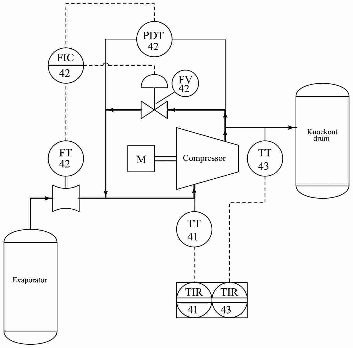
Figure 2: Process and Instrument Diagrams
The PID offers an instrumental representation of the control equipment required in the distillation column hence, it is an important document of the project. On the PID, it is possible to see the distribution of various sensors, transmitters, controllers, and final control elements giving a broad and adequate control of the process. Several components that are part of the PID are shown as follows: temperature sensor and pressure sensor which is used to measure process variables on various parts of the column. These values are communicated to the controllers and these in return convert the signals to signals that control various final control devices such as the control valves and so on to contain the desired operating conditions (Biasi et al., 2021). The PID also indicates other safety gears are pressure safety valves, which work to prevent pressure occurrences such as over pressure.
4.2 Control Strategy
| Control Loop | Description | Control Strategy |
| Temperature Control (Reboiler) | Maintains the reboiler temperature to ensure efficient vaporization. | Feedback control loop with a temperature transmitter and controller adjusting the heat input. |
| Temperature Control (Top) | Controls the top temperature to achieve the desired distillate composition. | Feedback control loop with a temperature transmitter and controller adjusting the reflux flow rate. |
| Pressure Control | Maintains the column pressure at atmospheric conditions. | Pressure control valve with a pressure transmitter and controller. |
| Level Control (Reboiler) | Maintains the liquid level in the reboiler to prevent dry-out or flooding. | Level control valve with a level transmitter and controller. |
| Level Control (Condenser) | Maintains the liquid level in the condenser to ensure efficient condensation. | Level control valve with a level transmitter and controller. |
| Flow Control (Feed) | Regulates the feed flow rate into the column. | Flow control valve with a flow transmitter and controller. |
| Flow Control (Reflux) | Controls the reflux flow rate to maintain the desired reflux ratio. | Flow control valve with a flow transmitter and controller. |
Table 1: Strategy table
4.3 Startup / shutdown / emergency procedures
4.3.1 Startup Procedures
Pre-Startup Checks:
A preliminary inspection of the distillation column and accessory devices should be made prior to the startup of the process. Make sure that all parts are in good order and that there are no crack or leaks especially on the parts that directly come into contact with hot water. Check that all safety related equipment such as the pressure relief devices and the emergency shutdown equipment are in good working condition (Li et al., 2025). Asses the stocking level of the chemicals so that the required amounts are in the factory to cater for the manufacturing process ascertain the availability of necessities such as cooling water and steam.
Initial Feed Introduction:
First, it is gradually to provide the feed mixture into a column. the methods for regulating the flow of the liquid is to cautiously open the feed valve and allow the liquid to flow to the column through the bottom then rising upwards. This minimizes the shock that may be exerted on the column and also makes sure that temperatures are well distributed throughout the height of the column (Du et al., 2023). It is also advisable to check if the feed rate of the system at hand complies with the overall rated feed rate of the structure.
Heating and Pressurization:
Start the reboiler to heat the liquid that is at the bottom of the column. The temperature profile within the column should be set into the desired level, and it should be done gradually by increasing the heat input. At the same time, turn on the condenser in order to take heat from the vapor on top of the column, and to set the right pressure difference. Check temperature and pressure of the hydrocarbon at several differential spots of the column as it should not go beyond a certain limit.
Establishing Reflux:
After the column reaches the proper temperature and pressure for the system, set the rate of reflux flow. By doing so, adjust the reflux valve in order to obtain the necessary reflux coefficient, that is the composition of the distillate product. Some specifications that are present on the vapour-liquid contactor include monitoring the reflux flow rate and reflux composition.
Ramping Up to Full Operation:
Increment the feeding rate and heat supply so as to attain full working parameters slowly and steadily. Observe the operation of the column carefully and adjust the feed rate, the amount of reflux and heat input for the proper functioning of the column (Kabeyi and Olanrewaju, 2022). Always ensure that the column works within the controlled limit before moving to normal flows.
5. Hazards
5.2 Mitigation of Hazards
Some of these hazards include; Because of this, risks within the distillation column design must be minimised/controlled so as to achieve optimal functioning. There are several ways of managing the risks which include:
Pressure Relief Systems: The pressure safety valve is used to relieve pressure with the specific aim of avoiding destructive pressure levels and possible hazards within equipment (Gao et al., 2023). That is why it is imperative to perform an operational check of these valves systematically and on a regular basis.
Emergency Shutdown Systems: This is such a system that shutdown systems of a plant, machinery or a process, when in case of emergency or threatening occurrences. Others are the shutting down sequences which stop the column by closing the valves, and the stalling of the pumps. Such incorporates issues to do with inspection and maintenance of vehicles and structures where activities such as checking for faults are done regularly (Chen et al., 2021). This is done to ensure the equipment is not corroded, has no leakage and is not worn out in certain areas that are supposed to be more worn out.
Training: Fully fledged training programs enable the operators to obtain adequate knowledge and practical skills for emergency periods. This involves matters such as the control systems, emergency drills or procedures and safety measures.
Redundant Control Systems/Backup Control Systems: Putting into practice backup control systems guarantees that operations of critical process variables are checked and regulated even in the event that the main systems collapse (Markowski et al., 2022). This feature offers an added security measure that ensures its reliability.
Preventing Leaks and Spills: Containment measures in case of leaks or spills and the plan on how to deal with spills are well established to prevent threats to the environment and individuals (Neukäufer et al., 2023). This is by having appropriate absorbent materials and other barriers in place established.
6 Economic evaluation
6.1 Capital Cost Assessment
The requirements for capital cost incorporates determining the costs expenses required in terms of manufacturing, procurement, and installation of necessary equipment and systems in the distillation column.
The major cost of equipment includes cost of distillation column, reboiler, condenser, feed pump and control valves which are all part of the initial fixed capital investment (Javed et al., 2022). These costs are estimated based on today’s data, using prices of various equipment and devices according to the project and its characteristics.
Engineering and Design: As it will be seen from the cost breakdown, the cost of engineering service to design the column, other equipment shown in the process as well as control systems is high. These are complex aspects such as the engineering drawings, logical simulations of the process, and the safety review of the entire procedure.
Construction and Installation: To some extent, the costs pertaining to the construction and installation of the column and peripherals are fairly high (Ayuso et al., 2022). These are mainly the site work and civil constructions as well as pipelines, electrical and instrumentations.
Contingency: Contingency fund is money provided for expenditure that may occur as the project is being implemented but could not have been foreseen at the time of making the estimates (Liu et al., 2022). This stands between 10-15 % of the total capital cost to allow for flexibility of finance in case of an occurrence of obstacles.
Permitting and Compliance: Other costs generated from permitting and compliance to environmental and safety standards are also included (Zhu et al., 2021). These are the fees for licences, impact costs, and safety compliances of the location chosen or needed for the implementation of the project.
7 Conclusions
7.1 Conclusion/Summary of Key Findings
Conclusively, the distillation column design, in effect, realizes the objectives of the project, and provides an efficient process for the separation of hydrocarbons. As illustrated by some of the crucial observations, the column with sieve trays and the respective control systems provides the best separation of the hydrocarbon components as per the desired product specifications. In the same forums, the enhancement of several types of control methods ensures a consistent operation and smooth functioning of the process in case of fluctuations in the process. Pressure relief and safe shutdown systems are also very good which has greatly reduced the exposure to various dangers thereby achieving good safety while the plant is operating. For the economic evaluation, cost of capital test the viability of the proposed operation and concluded that the NPV for the project was positive as well as the payback period had been favorable. In future, non-suspending and further improvement of the control systems and upkeep routines will only improve the quality and reliability of the column. This informs us that future studies and other simulation practices will give a clear way forward on how other enhancements and innovations that can be implemented to enhance the performance of distillation column can be achieved.
Reference List
Journals
- Zhang, M.J., Croiset, E. and Ioannidis, M., 2022. Constructivist-based experiential learning: A case study of student-centered and design-centric unit operation distillation laboratory. Education for Chemical Engineers, 41, pp.22-31.
- Kong, Z.Y., Adi, V.S.K., Segovia-Hernández, J.G. and Sunarso, J., 2023. Complementary role of large language models in educating undergraduate design of distillation column: Methodology development. Digital Chemical Engineering, 9, p.100126.
- Martínez, J.D., Sanchís, A., Veses, A., Callén, M.S., López, J.M., García, T. and Murillo, R., 2024. Design and operation of a packed pilot scale distillation column for tire pyrolysis oil: Towards the recovery of value-added raw materials. Fuel, 358, p.130266.
- Stichlmair, J.G., Klein, H. and Rehfeldt, S., 2021. Distillation: principles and practice. John Wiley & Sons.
- Waibel, Y., Trescher, L., Ränger, L.M. and Grützner, T., 2023. First multiple dividing wall column: Design and operation. Chemical Engineering Research and Design, 193, pp.132-144.
- Yadav, E.S., Indiran, T., Nayak, D., Kumar, C.A. and Selvakumar, M., 2022. Simulation study of distillation column using Aspen plus. Materials Today: Proceedings, 48, pp.330-337.
- Halager, N.S., Bayer, C., Kirkpatrick, R., Gernaey, K.V., Huusom, J.K. and Udugama, I.A., 2021. Modelling and control of an integrated high purity methanol distillation configuration. Chemical Engineering and Processing-Process Intensification, 169, p.108640.
- Biasi, L.C., Romano, A.L., Zemp, R.J., Heinkenschloss, M., Batista, F.R. and Meirelles, A.J., 2021. Distillation columns with multiple phase divisions: how they improve thermodynamic efficiency and decrease energy consumption. Industrial & Engineering Chemistry Research, 60(43), pp.15690-15705.
- Gao, S., Lu, Y., Ooi, C.H., Cai, Y. and Gunawan, P., 2023. Designing interactive augmented reality application for student's directed learning of continuous distillation process. Computers & Chemical Engineering, 169, p.108086.
- Chen, H., Zhao, L., Cong, H. and Li, X., 2021. Robust solar-energy system design and optimisation for reactive distillation column in methyl acetate hydrolysis process. Energy Conversion and Management, 243, p.114426.
- Markowski, M., Trafczynski, M. and Kisielewski, P., 2022. The dynamic model of a rectification heat exchanger using the concept of heat-integrated distillation column. Energy, 256, p.124622.
- Neukäufer, J., Ashour, M.A., Sarajlic, N., Klein, H., Rehfeldt, S., Hallmann, H., Meinicke, S., Paschold, J., Knösche, C. and Grützner, T., 2023. Development of enhanced three‐dimensional printed packings for scale‐up of distillation columns: A successful case study. AIChE Journal, 69(3), p.e17902.
- Ayuso, M., Navarro, P., Moya, C., Moreno, D., Palomar, J., García, J. and Rodríguez, F., 2022. Extractive distillation with ionic liquids to separate benzene, toluene, and xylene from pyrolysis gasoline: process design and techno-economic comparison with the morphylane process. Industrial & Engineering Chemistry Research, 61(6), pp.2511-2523.
- Zhu, J., Hao, L. and Wei, H., 2021. Sustainable concept design including economic, environment and inherent safety criteria: Process intensification-reactive pressure swing distillation. Journal of Cleaner Production, 314, p.127852.
- Javed, A., Hassan, A., Babar, M., Azhar, U., Riaz, A., Mujahid, R., Ahmad, T., Mubashir, M., Lim, H.R., Show, P.L. and Khoo, K.S., 2022. A comparison of the exergy efficiencies of various heat-integrated distillation columns. Energies, 15(18), p.6498.
- Liu, J., Yan, J., Liu, W., Kong, J., Wu, Y., Li, X. and Sun, L., 2022. Design and multi-objective optimization of reactive-extractive dividing wall column with organic Rankine cycles considering safety. Separation and Purification Technology, 287, p.120512.
- Quader, M.A., Rufford, T.E. and Smart, S., 2021. Integration of hybrid membrane-distillation processes to recover helium from pre-treated natural gas in liquefied natural gas plants. Separation and Purification Technology, 263, p.118355.
- Finberg, E.A. and Shiflett, M.B., 2021. Process designs for separating R-410A, R-404A, and R-407C using extractive distillation and ionic liquid entrainers. Industrial & Engineering Chemistry Research, 60(44), pp.16054-16067.
- Li, Q., Finn, A.J., Doyle, S.J., Smith, R. and Kiss, A.A., 2023. Synthesis and optimization of energy integrated advanced distillation sequences. Separation and Purification Technology, 315, p.123717.
- Cui, C., Zhang, X., Lyu, H., Wang, S., Sun, J., Qu, Y., Wu, W., Bo, C., Wong, D.S.H. and Zhang, Q., 2021. Process intensification in ternary distillation via comparative grassroots and retrofit designs: A case study of distilling an industrial multicomponent C6 alkane mixture in caprolactam processing. Chemical Engineering and Processing-Process Intensification, 164, p.108423.
- Yusuf, N. and Almomani, F., 2023. Recent advances in biogas purifying technologies: Process design and economic considerations. Energy, 265, p.126163.
- Dahal, R., Uusi-Kyyny, P., Pokki, J.P., Ohra-aho, T. and Alopaeus, V., 2023. Conceptual design of a distillation process for the separation of styrene monomer from polystyrene pyrolysis oil: experiment and simulation. Chemical Engineering Research and Design, 195, pp.65-75.
- Wang, L., Yang, A., Chang, C., Qiu, T., Yang, C., Lei, Z., Mo, W., Tao, H., Wang, B., Hu, X. and Shen, W., 2025. A general distillation strategy and energy-efficient process design for optimal sequence screening in complicated homologue-azeotrope coexisting system. Separation and Purification Technology, p.132204.
- Sagi, B. and Thyagarajan, T., 2025. Model Independent Dynamic Predictive Controller Design Using Differential Extreme Learning Machine for Composition Control in Binary Distillation Column. International Journal of Adaptive Control and Signal Processing, 39(2), pp.332-343.
- Zhong, J., Cheng, H., Dai, Y., Jiao, Y., Wang, K., Xin, L., Zhang, Y., Zhu, Z., Cui, P., Lu, Y. and Wang, Y., 2023. Design and multiple performance evaluation of green sustainable process for azeotropes separation via extractive distillation. ACS Sustainable Chemistry & Engineering, 11(48), pp.16849-16881.
- Shen, T., Teng, L., Hu, Y. and Shen, W., 2023. Systematic screening procedure and innovative energy-saving design for ionic liquid-based extractive distillation process. Frontiers of Chemical Science and Engineering, 17(1), pp.34-45.
- Bhat, V.S., Bhat, S., Indiran, T., Selvanathan, S.P., Gijo, E.V., Antony, J., Pepper, M. and Foster, S.T., 2025. Managing quality by design for sustainable performance in the process industry. Quality Management Journal, 32(1), pp.30-52.
- Tsai, C.Y., Ang, T., Kong, Z.Y., Sunarso, J. and Adi, V.S.K., 2023. Toward a flexible design for the bioethanol dehydration using extractive distillation. Part 1: steady-state design and optimization. Industrial & Engineering Chemistry Research, 62(51), pp.22043-22057.
- Yan, J., Liu, J., Ren, J., Wu, Y., Li, X., Sun, T. and Sun, L., 2022. Design and multi-objective optimization of hybrid reactive-extractive distillation process for separating wastewater containing benzene and isopropanol. Separation and Purification Technology, 290, p.120915.
- Yang, A., Su, Y., Shi, T., Ren, J., Shen, W. and Zhou, T., 2022. Energy-efficient recovery of tetrahydrofuran and ethyl acetate by triple-column extractive distillation: entrainer design and process optimization. Frontiers of Chemical Science and Engineering, pp.1-13.
- Pistikopoulos, E.N., Tian, Y. and Bindlish, R., 2021. Operability and control in process intensification and modular design: Challenges and opportunities. AIChE Journal, 67(5), p.e17204.
- Lewin, D.R. and Barzilai, A., 2021. Teaching Process Design to Chemical Engineering Undergraduates at the Technion–an Evolution. Chemical Engineering Education, 55(3), pp.157-172.
- Soltani Panah, H. and Jeong, D.H., 2025. Pyrolysis Products Separation of Lignin via Molecular Distillation and Liquid–Liquid Extraction. Korean Journal of Chemical Engineering, pp.1-16.
- Liu, J., Ren, J., Yang, Y., Liu, X. and Sun, L., 2021. Effective semicontinuous distillation design for separating normal alkanes via multi-objective optimization and control. Chemical Engineering Research and Design, 168, pp.340-356.
- Yan, J., Liu, J., Ren, J., Wu, Y., Li, X., Sun, T. and Sun, L., 2022. Design and multi-objective optimization of hybrid reactive-extractive distillation process for separating wastewater containing benzene and isopropanol. Separation and Purification Technology, 290, p.120915.
- Wang, K., Xin, L., Zhang, Y., Qi, J., Zhu, Z., Wang, Y., Zhong, L. and Cui, P., 2024. Sustainable and efficient process design for wastewater recovery of cyclohexane/isopropyl alcohol azeotrope by extractive distillation based on multi-objective genetic algorithm optimization. Chemical Engineering Research and Design, 201, pp.593-602.
- Semenov, A., Podkamennyi, Y., Bebikhov, Y. and Yakushev, I., 2023. Saving the environment by automation of crude oil distillation in a rectification column. In E3S Web of Conferences (Vol. 371, p. 01093). EDP Sciences.
- Pistikopoulos, E.N., Tian, Y. and Bindlish, R., 2021. Operability and control in process intensification and modular design: Challenges and opportunities. AIChE Journal, 67(5), p.e17204.
- Tian, Y., Pappas, I., Burnak, B., Katz, J. and Pistikopoulos, E.N., 2021. Simultaneous design & control of a reactive distillation system–a parametric optimization & control approach. Chemical Engineering Science, 230, p.116232.
- Lewin, D.R. and Barzilai, A., 2021. Teaching Process Design to Chemical Engineering Undergraduates at the Technion–an Evolution. Chemical Engineering Education, 55(3), pp.157-172.
- Liu, J., Ren, J., Yang, Y., Liu, X. and Sun, L., 2021. Effective semicontinuous distillation design for separating normal alkanes via multi-objective optimization and control. Chemical Engineering Research and Design, 168, pp.340-356.
- Nhien, L.C., Long, N.V.D. and Lee, M., 2021. Novel hybrid reactive distillation with extraction and distillation processes for furfural production from an actual xylose solution. Energies, 14(4), p.1152.
- Yang, A., Wang, W., Sun, S., Shi, T., Ren, J., Bai, M. and Shen, W., 2022. Sustainable design and multi-objective optimization of eco-efficient extractive distillation with single and double entrainer (s) for separating the ternary azeotropic mixture tetrahydrofuran/ethanol/methanol. Separation and Purification Technology, 285, p.120413.
- Xia, M., Neumann, M., Rehfeldt, S. and Klein, H., 2023. Improving design and scale-up of columns with structured packings by means of CFD. Chemical Engineering Research and Design, 193, pp.54-64.
- Beneroso, D. and Robinson, J., 2021. A tool for assessing and providing personalised formative feedback at scale within a second in engineering courses. Education for Chemical Engineers, 36, pp.38-45.
- Xu, Q., Dai, Y., Zhao, Q., Chen, Z., Cui, P., Zhu, Z., Wang, Y., Gao, J. and Ma, Y., 2023. Economy, environmental assessment and energy conservation for separation of isopropanol/diisopropyl ether/water multi-azeotropes via extractive distillation coupled pervaporation process. Chinese Journal of Chemical Engineering, 54, pp.353-363.
- Herink, T., Bělohlav, V., Jirout, T. and Bělohlav, Z., 2022. Opportunities of experiential education in chemical technology and engineering. Education for Chemical Engineers, 41, pp.32-41.
- Kong, J., Wan, G., Yan, J., Yi, Q., Hao, X., Liu, X. and Sun, L., 2023. Design and control of extraction combined with extractive distillation for separation isopropanol-butanol-ethanol-water with organic Rankine cycle. Separation and Purification Technology, 313, p.123443.
- Yang, A., Kong, Z.Y., Sun, S., Sunarso, J., Ren, J. and Shen, W., 2023. Design and multiobjective optimization of a novel double extractive dividing wall column with a side reboiler scheme for the recovery of ethyl acetate and methanol from wastewater. Industrial & Engineering Chemistry Research, 62(44), pp.18591-18602.
- Du, L., Jin, S., Yang, Z., Sun, S., Yang, A. and Shen, W., 2023. An efficient multi-criteria decision making for assessing the optimization of reactive extractive distillation in terms of economy, environment and safety. Chemical Engineering Research and Design, 197, pp.838-850.
- Li, M., Xu, H. and Tian, H., 2025. Design and control of an extractive distillation process for separating isopropanol and water with side-stream extraction. Chinese Journal of Chemical Engineering.
- Kabeyi, M.J.B. and Olanrewaju, O.A., 2022. Performance analysis and evaluation of ethanol potential of Nzoia Sugar Company Ltd. Energy Reports, 8, pp.787-799.